SV-iS7 User Manual - Inverter Drive Supermarket
SV-iS7 User Manual - Inverter Drive Supermarket
SV-iS7 User Manual - Inverter Drive Supermarket

You also want an ePaper? Increase the reach of your titles
YUMPU automatically turns print PDFs into web optimized ePapers that Google loves.
Chapter 8 Applied Functions<br />
For example, if APP-20 Ref Source is selected as No. 1 V1 terminal, the inputs other than V1 should be selected in APP-<br />
21 PID F/B Source. Set as No. 18 PID Fdb Value of CNF-06~08, the feedback can be monitored.<br />
APP-22 PID P-Gain, APP-26 P Gain Scale : Sets the output ratio of the difference(error) between the reference and<br />
feedback. If P gain is set at 50%, 50% of the error is output. The setting range of P gain is 0.0~1000.0%. If a ratio lower<br />
than 0.1% is necessary, use P Gain Scale of APP-26.<br />
APP-23 PID I-Time : Sets the times for output of accumulated errors. This sets the time for 100% output when the error is<br />
100%. If the integral time(PID I-Time) is set at 1 second, 100% is output after 1 second when the error is 100%. The<br />
normal error can be reduced by the integral time. If the multi-function terminal block function is set at 21 I-Term Clear and<br />
the terminal block is ON, all the accumulated integral amount is deleted.<br />
APP-24 PID D-Time : Sets the output of the error change rate. If the differential time(PID D-Time) is set at 1mSec, 1% is<br />
output per 10mSec when the error change rate per second is 100%.<br />
APP-25 PID F-Gain : The set goal can be added to the PID output and the ratio is set. This can obtain a rapid response<br />
characteristic.<br />
APP-27 PID Out LPF : This is used when the entire system is instable because the PID controller output changes too fast<br />
or there is too much oscillation. Normally the responsiveness is enhanced by using a low value(the initial value is 0) but the<br />
stability can also be improved by using a higher value. The higher a value is used, the more stable the PID controller<br />
output is but the responsiveness might be down.<br />
APP-29 PID Limit Hi, APP-30 PID Limit Lo : Limits the output of the PID controller.<br />
APP-32 PID Out Scale : Adjusts the size of the controller output.<br />
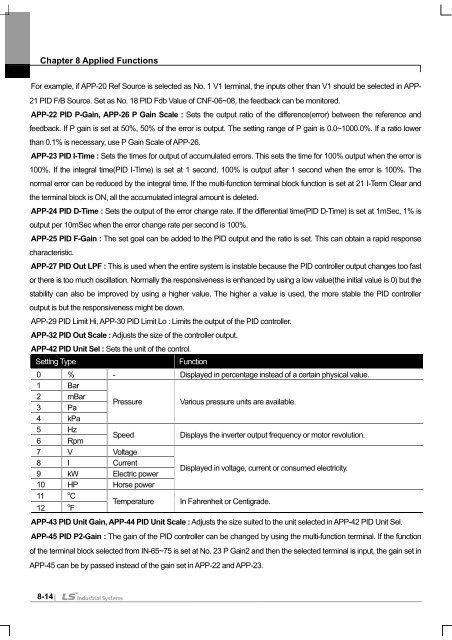
APP-42 PID Unit Sel : Sets the unit of the control.<br />
Setting Type Function<br />
0 % - Displayed in percentage instead of a certain physical value.<br />
1 Bar<br />
2<br />
3<br />
mBar<br />
Pa<br />
Pressure Various pressure units are available.<br />
4 kPa<br />
5<br />
6<br />
Hz<br />
Rpm<br />
Speed Displays the inverter output frequency or motor revolution.<br />
7 V Voltage<br />
8<br />
9<br />
I<br />
kW<br />
Current<br />
Electric power<br />
Displayed in voltage, current or consumed electricity.<br />
10 HP Horse power<br />
11<br />
12<br />
o<br />
C<br />
o<br />
F<br />
Temperature In Fahrenheit or Centigrade.<br />
APP-43 PID Unit Gain, APP-44 PID Unit Scale : Adjusts the size suited to the unit selected in APP-42 PID Unit Sel.<br />
APP-45 PID P2-Gain : The gain of the PID controller can be changed by using the multi-function terminal. If the function<br />
of the terminal block selected from IN-65~75 is set at No. 23 P Gain2 and then the selected terminal is input, the gain set in<br />
APP-45 can be by passed instead of the gain set in APP-22 and APP-23.<br />
8-14