SV-iS7 User Manual - Inverter Drive Supermarket
SV-iS7 User Manual - Inverter Drive Supermarket
SV-iS7 User Manual - Inverter Drive Supermarket

Create successful ePaper yourself
Turn your PDF publications into a flip-book with our unique Google optimized e-Paper software.
Chapter 8 Applied Functions<br />
2) If there are four motors in total and the auto change mode selection(APO-35) is set at 2(Main), the operation is as<br />
follows. If the starting auxiliary motor selection APO-21 is set at 1, motor 1 is operated by the inverter and the<br />
remaining 2, 3 and 4 are operated by the auxiliary motors and interlock signals are input to the auxiliary motors, the<br />
operation sequence is the same as the procedure described in 1) above. However if there is a problem with motor 1,<br />
which is connected to the inverter, the output is immediately blocked and motor 2 gets connected to the inverter<br />
output and the operation sequence of the auxiliary motor is 3, 4. If the interlock signal of motor 1 is withdrawn, the<br />
operation sequence of the auxiliary motor is 3, 4, 1.<br />
Bypass Operation (Regul Bypass)<br />
The speed of the main motor can be controlled by the feedback without using the PID. The operation and stop of<br />
the auxiliary motor is controlled according to the feedback amount.<br />
APP-34 Regul Bypass : Select No. 1 Yes. If there are four main motors and auxiliary motors(APP-33) in total, the<br />
operation is as follows. If the feedback input value is between 0~10V and operating frequency of the maximum input<br />
value(10V) is 60Hz, the auxiliary motor 1 is started when the feedback amount is 2.5V(15Hz of main motor<br />
operating frequency). If the feedback amount reaches 5V again, the auxiliary motor 2 is operated. At maximum 10V<br />
input, all three auxiliary motors operated.<br />
Operation level of auxiliary motor n<br />
8.1.40 Regeneration evasion function for press<br />
(To evade control operation in the status of regeneration during press)<br />
Maximum feedback amount<br />
= n ∗<br />
The number of auxiliary motor(<br />
APO − 33)<br />
This function is the one to prevent regeneration region, raising the speed of motor operation speed during press in the<br />
status of motor regeneration.<br />
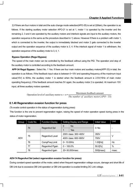
Group Code No. Function Display Setting Display and Range Initial Value Unit<br />
74 RegenAvd Sel<br />
0<br />
1<br />
No<br />
Yes<br />
0: No -<br />
ADV<br />
75 RegenAvd Level<br />
200V class: 300~400V<br />
400V class: 600~800V<br />
350V<br />
700V<br />
V<br />
76 CompFreq Limit 0~ 10.00Hz 1.00[Hz] Hz<br />
77 RegenAvd Pgain 0 ~ 100.0% 50.0[%] %<br />
78 RegenAvd Igain 20~30,000msec 500[msec] msec<br />
ADV-74 RegenAvd Sel (select regeneration evasion function for press):<br />
During constant speed operation of the motor, select when frequent regeneration voltage occurs, damage and short life of<br />
DB Unit due to excessive DB Unit operation or DB Unit operation is evaded limiting DC Link voltage.<br />
8-61