SV-iS7 User Manual - Inverter Drive Supermarket
SV-iS7 User Manual - Inverter Drive Supermarket
SV-iS7 User Manual - Inverter Drive Supermarket

You also want an ePaper? Increase the reach of your titles
YUMPU automatically turns print PDFs into web optimized ePapers that Google loves.
Input signal<br />
Output Signal<br />
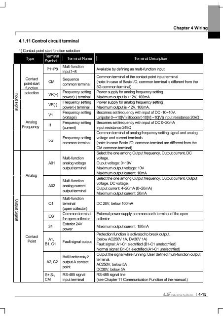
4.1.11 Control circuit terminal<br />
Chapter 4 Wiring<br />
1) Contact point start function selection<br />
Type<br />
Terminal<br />
Symbol<br />
Terminal Name Terminal Description<br />
P1~P8 Multi-function<br />
input1~8<br />
Available by defining as multi-function input<br />
Contact<br />
point start<br />
function<br />
selection<br />
CM<br />
VR(+)<br />
Sequence<br />
common terminal<br />
Frequency setting<br />
power(+) terminal<br />
Common terminal of the contact point input terminal<br />
(note: In case of Basic I/O, common terminal is different from the<br />
5G common terminal)<br />
Power supply for analog frequency setting<br />
Maximum output is +12V, 100mA.<br />
VR(-)<br />
Frequency setting<br />
power(-) terminal<br />
Power supply for analog frequency setting<br />
Maximum output is -12V, 100mA.<br />
V1<br />
Frequency setting<br />
(voltage)<br />
Becomes set frequency with input of DC -10~10V.<br />
Unipolar 0~+10[V]),Biopolar(-10[V] ~10[V]) input resistance 20kΩ<br />
Analog<br />
Frequency<br />
I1<br />
Frequency setting<br />
(current)<br />
Becomes set frequency with input of DC 0~20mA<br />
input resistance 249Ω<br />
Common terminal of analog frequency setting signal and analog<br />
5G<br />
Frequency setting<br />
common terminal<br />
voltage and current terminals<br />
(note: In case Basic I/O, common terminal are different from the<br />
CM common terminal)<br />
Select the one among Output frequency, Output current, DC<br />
Multi-function voltage.<br />
A01 analog voltage Ouput voltage: 0~10V<br />
output terminal Maximum output voltage: 10V<br />
Analog<br />
A02<br />
Multi-function<br />
analog current<br />
output terminal<br />
Multi-function<br />
Maximum output current: 10mA<br />
Select the one among Output frequency, Output current, Output<br />
voltage, DC voltage.<br />
Output current: 4~20mA (0~20mA)<br />
Maximum output current: 20mA<br />
Q1 terminal<br />
(open collector)<br />
DC 26V, below 100mA<br />
EG<br />
Common terminal<br />
for open collector<br />
External power supply common earth terminal of the open<br />
collector<br />
24<br />
Exterior 24V<br />
power<br />
Maximum output current: 150mA<br />
Contact<br />
Point<br />
A1,<br />
B1, C1<br />
Fault signal output<br />
Protection function is activated to break output.<br />
(below AC250V 1A, DV30V 1A)<br />
Fault signal: A1-C1 electrified (B1-C1 unelectrified)<br />
Normal signal: B1-C1 electrified (A1-C1 unelectrified)<br />
A2, C2<br />
Multi-function relay 2<br />
output A contact<br />
point<br />
Output the signal while running. <strong>User</strong> defined multi-function output<br />
terminal.<br />
AC250V, below 5A<br />
DC30V, below 5A<br />
S+,S-, RS-485 signal RS-485 signal line<br />
CM input terminal (see Chapter 11 Communication Function of the manual.)<br />
4-15