SV-iS7 User Manual - Inverter Drive Supermarket
SV-iS7 User Manual - Inverter Drive Supermarket
SV-iS7 User Manual - Inverter Drive Supermarket

You also want an ePaper? Increase the reach of your titles
YUMPU automatically turns print PDFs into web optimized ePapers that Google loves.
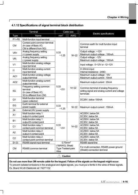
4.1.12 Specifications of signal terminal block distribution<br />
Chapter 4 Wiring<br />
Type<br />
Terminal<br />
Name<br />
Cable size<br />
mm 2 AWG<br />
Electric specifications<br />
P1~P8 Multi-function input terminal -<br />
CM<br />
Contact point common terminal<br />
(In case of Basic I/O,<br />
CM is different from 5G)<br />
Common earth for multi function input<br />
terminal<br />
VR+<br />
VR-<br />
Analog frequency setting<br />
(+) power supply<br />
Analog frequency setting<br />
(-) power supply<br />
0.33<br />
~1.25 16~22<br />
Output voltage : +12V<br />
Maximum output voltage : 100mA<br />
Output voltage : -12V<br />
Maximum output voltage : 100mA<br />
V1<br />
Multi-function analog voltage<br />
input terminal<br />
Input voltage : 0~12V or -12~12V<br />
I1<br />
Multi-function analog current<br />
input terminal<br />
0~20mA input<br />
Internal resistance : 249Ω<br />
AO1<br />
Multi-function analog voltage<br />
output terminal<br />
Maximum output voltage : 10V<br />
Maximum output current : 10mA<br />
AO2<br />
Multi-function analog current<br />
output terminal<br />
Maximum output current : 20mA<br />
5G<br />
Frequency setting common<br />
terminal<br />
(In case of Basic I/O,<br />
5G is different from CM)<br />
0.33<br />
~2.0<br />
14~22 Common terminal of analog frequency<br />
setting signal and analog current and voltage<br />
terminals<br />
Q1<br />
Multi-function terminal<br />
(open collector)<br />
DC26V, below 100mA<br />
EG<br />
24<br />
Earth terminal for external<br />
power supply<br />
External 24V power supply<br />
0.33<br />
~1.25<br />
16~22 Maximum output current : 150mA<br />
A1<br />
Multi function relay 1<br />
output A contact point<br />
AC250V, below 5A<br />
DC30V, below 5A<br />
B1<br />
Multi function relay 1<br />
output B contact point<br />
AC250V, below 5A<br />
DC30V, below 5A<br />
C1<br />
Multi function relay 1<br />
contact point common terminal<br />
0.33<br />
~2.0<br />
14~22<br />
AC250V, below 5A<br />
DC30V, below 5A<br />
A2<br />
Multi function relay 2<br />
output A contact point<br />
AC250V, below 5A<br />
DC30V, below 5A<br />
C2<br />
Multi function relay 2<br />
contact point common terminal<br />
AC250V, below 5A<br />
DC30V, below 5A<br />
S+,S- RS485 signal input terminal 0.75mm RS485 signal line<br />
CM RS485 common terminal<br />
2<br />
(18AWG), Shield<br />
Type Twisted-pare<br />
Wire<br />
For multi connection, RS485 power ground<br />
(Shield) connection terminal<br />
Caution<br />
Do not use more than 3M remote cable for the keypad. Failure of the signals on the keypad might occur.<br />
To prevent radiated emissions in the analogical and digital signals, you must put a ferrite in the wires of these signals.<br />
Ex. Brand Würth Elektronik ref. 74271132<br />
4-16