SV-iS7 User Manual - Inverter Drive Supermarket
SV-iS7 User Manual - Inverter Drive Supermarket
SV-iS7 User Manual - Inverter Drive Supermarket

Create successful ePaper yourself
Turn your PDF publications into a flip-book with our unique Google optimized e-Paper software.
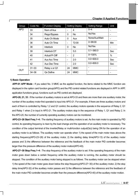
Chapter 8 Applied Functions<br />
Group Code No. Function Display Setting Display Setting Range Unit<br />
APO 33 Num of Aux - 4 0~4 -<br />
OUT<br />
34 Regul Bypass 0 No No/Yes -<br />
35 Auto Ch Mode 0 Aux None/Aux/Main -<br />
36 Auto Ch Time - 72:00 0~99:00 Min<br />
38 Interlock 0 No No/Yes -<br />
39 Interlock DT - 5.0 0.1~360.0 Sec<br />
40 Actual Pr Diff - 2 0~100% %<br />
41 Aux Acc Time - 2.0 0.0~600.0 Sec<br />
42 Aux Dec Time - 2.0 0.0~600.0 Sec<br />
31~33 Relay x or Q1 24 MMC - -<br />
34~36 Qx Define 24 MMC - -<br />
1) Basic Operation<br />
APP-01 APP Mode : If you select No. 3 MMC as the applied function, the items related to the MMC function are<br />
displayed in the option card function group(APO) and the PID control related functions are displayed in APP. In APP,<br />
application functions group, functions such as PID control are displayed.<br />
APO-20, 21, 33 : If the number of auxiliary motors is set at APO-33 and there are more than one auxiliary motor, the<br />
number of the auxiliary motor first operated is input into APO-21. For example, if there are three auxiliary motors and<br />
each of them is controlled by Relay 1,2 and Q1 control, the auxiliary motors operate in the sequence of Relay 2, Q1<br />
and Relay 1 when 2 in input in APO-21. The auxiliary motors stop in the sequence of Relay 1, Q1 and Relay 2. In<br />
the APO-20, the number of currently operating auxiliary motors can be monitored.<br />
APO-23~26 Start Freq 1~4 : The starting frequency of auxiliary motors is set. As the main motor is operated by PID<br />
control, its operating frequency is risen by the load change and the operation of an auxiliary motor is necessary. The<br />
condition of the output terminal of the inverter(Relay or multi-function output(Qx)) being ON for the operation of an<br />
auxiliary motor is as follows. The auxiliary motor can operate when 1) the speed of the main motor rises above the<br />
starting frequency(APO-23~26) of the auxiliary motor, 2) the starting delay time(APO-13) of the auxiliary motor<br />
passes and 3) the difference between the reference and the feedback of the main motor PID controller becomes<br />
larger than the pressure difference of the auxiliary motor motion(APO-40).<br />
APO-27~30 Stop Freq 1~4 : The stop frequency of the auxiliary motor is set. If the operating frequency of the main<br />
motor goes down below a certain frequency while the auxiliary motor is running, the auxiliary motor should be<br />
stopped. The condition of the auxiliary motor being stopped is as follows. The auxiliary motor can be stopped when<br />
1) the speed of the main motor goes down below the stop frequency(APO-27~30) of the auxiliary motor, 2) the stop<br />
delay time(APO-32) of the auxiliary motor passes and 3) the difference between the reference and the feedback of<br />
the main motor PID controller becomes smaller than the pressure difference(APO-40) of the auxiliary motor motion.<br />
8-57