- Page 1 and 2:
Right choice for ultimate yield LSI
- Page 3 and 4:
ii WARNING � Do not remove the co
- Page 5 and 6:
iv Environment (2) Wiring Ambient t
- Page 7 and 8:
Introduction to the Manual Introduc
- Page 9 and 10:
ii Contents 3.1.2 3.1.3 3.1.4 3.1.5
- Page 11 and 12:
Contents iv Chapter 7 Basic Functio
- Page 13 and 14:
Contents vi 8.1.24 Cooling fan cont
- Page 15 and 16:
Contents viii Chapter 11 Communicat
- Page 17 and 18:
x Contents 13.1.11 Parameter mode -
- Page 19 and 20:
Chapter 1 Basics 1-2 1.1.5 Distribu
- Page 21 and 22:
Chapter 2 Specifications 2-1 2.1 Sp
- Page 23 and 24:
Chapter 2 Specifications 2) Operati
- Page 25 and 26:
Chapter 3 Installation Note 3-2 Cau
- Page 27 and 28:
Chapter 3 Installation 3) SV0110-01
- Page 29 and 30:
Chapter 3 Installation 6) SV0550-07
- Page 31 and 32:
Chapter 3 Installation 8) SV1320-16
- Page 33 and 34:
Chapter 3 Installation 3-10 2) SV00
- Page 35 and 36:
Chapter 3 Installation 4) SV0185-02
- Page 37 and 38:
Chapter 3 Installation 3.1.5 Dimens
- Page 39 and 40:
Chapter 3 Installation 2) Mounting
- Page 41 and 42:
4.1 Wiring 4.1.1 How to separate fr
- Page 43 and 44:
4.1.2 How to separate front cover w
- Page 45 and 46:
3) How to set EMC Filter functions
- Page 47 and 48:
4.1.6 Terminal wiring diagram (POWE
- Page 49 and 50:
3) 90 ~ 160 kW (400V) R(L1) S(L2) T
- Page 51 and 52:
4.1.9 Control terminal line diagram
- Page 53 and 54:
1) Example of Distribution Relay2 (
- Page 55 and 56:
Input signal Output Signal 4.1.11 C
- Page 57 and 58:
4.2 Operation Checking Chapter 4 Wi
- Page 59 and 60:
5.1 Peripheral Devices Ground 5.1.1
- Page 61 and 62:
2) AC Reactor Specifications INVERT
- Page 63 and 64:
4) Dimensions - Group 1 - Group 2 5
- Page 65 and 66:
6.1 How to Use Keypad 6.1.1 Standar
- Page 67 and 68:
3) Composition of Display (1) Monit
- Page 69 and 70:
No Function Display Description FWD
- Page 71 and 72:
Chapter 6 How to Use Keypad 1) Para
- Page 73 and 74:
2) Mode Shift with User/Macro Mode
- Page 75 and 76:
PAR PRT N STP 0.00Hz 00 Jump Code 4
- Page 77 and 78:
2) Code shift (function Items) in o
- Page 79 and 80:
6.1.6 Parameter setting 1) Paramete
- Page 81 and 82:
6.1.7 Operating status monitoring 1
- Page 83 and 84:
3) How to use status display Chapte
- Page 85 and 86:
3) Saving and monitoring of failure
- Page 87 and 88:
7.1 Basic Functions 7.1.1 How to se
- Page 89 and 90:
Chapter 7 Basic Functions IN-05 V1
- Page 91 and 92:
The output frequency of bipolar vol
- Page 93 and 94:
Chapter 7 Basic Functions 5) Freque
- Page 95 and 96:
Chapter 7 Basic Functions If you se
- Page 97 and 98:
[Example of speed-8] Chapter 7 Basi
- Page 99 and 100:
Chapter 7 Basic Functions 4) Operat
- Page 101 and 102:
7.1.8 Run immediately with power On
- Page 103 and 104:
Caution Chapter 7 Basic Functions 9
- Page 105 and 106:
Chapter 7 Basic Functions You can c
- Page 107 and 108:
7.1.12 Acc/Dec Stop command Group C
- Page 109 and 110:
Chapter 7 Basic Functions The user
- Page 111 and 112:
Chapter 7 Basic Functions 7.1.16 Se
- Page 113 and 114:
Frequency Voltage Current Operating
- Page 115 and 116:
Chapter 7 Basic Functions (1) ADV-2
- Page 117 and 118:
7.1.21 Multi-function input termina
- Page 119 and 120:
Chapter 8 Applied Functions 8-2 Set
- Page 121 and 122:
Chapter 8 Applied Functions If 10.4
- Page 123 and 124:
Chapter 8 Applied Functions 8.1.3 U
- Page 125 and 126: Chapter 8 Applied Functions 8.1.5 S
- Page 127 and 128: Chapter 8 Applied Functions * Accel
- Page 129 and 130: Chapter 8 Applied Functions 8.1.8 P
- Page 131 and 132: Chapter 8 Applied Functions For exa
- Page 133 and 134: Chapter 8 Applied Functions 4) PID
- Page 135 and 136: Chapter 8 Applied Functions 8-18 In
- Page 137 and 138: Chapter 8 Applied Functions APO-05
- Page 139 and 140: Chapter 8 Applied Functions BAS-15
- Page 141 and 142: Chapter 8 Applied Functions Before
- Page 143 and 144: Chapter 8 Applied Functions lower O
- Page 145 and 146: Chapter 8 Applied Functions 1) Prep
- Page 147 and 148: Chapter 8 Applied Functions CON-48
- Page 149 and 150: Chapter 8 Applied Functions Group C
- Page 151 and 152: Chapter 8 Applied Functions If the
- Page 153 and 154: Chapter 8 Applied Functions 8.1.19
- Page 155 and 156: Chapter 8 Applied Functions ADV-61
- Page 157 and 158: Chapter 8 Applied Functions The car
- Page 159 and 160: Chapter 8 Applied Functions 8-42 Co
- Page 161 and 162: Chapter 8 Applied Functions 8.1.25
- Page 163 and 164: Chapter 8 Applied Functions 8-46 Ca
- Page 165 and 166: Chapter 8 Applied Functions 2) How
- Page 167 and 168: Chapter 8 Applied Functions CNF-42
- Page 169 and 170: Chapter 8 Applied Functions AUT-01
- Page 171 and 172: Chapter 8 Applied Functions 8.1.37
- Page 173 and 174: Chapter 8 Applied Functions 8.1.38
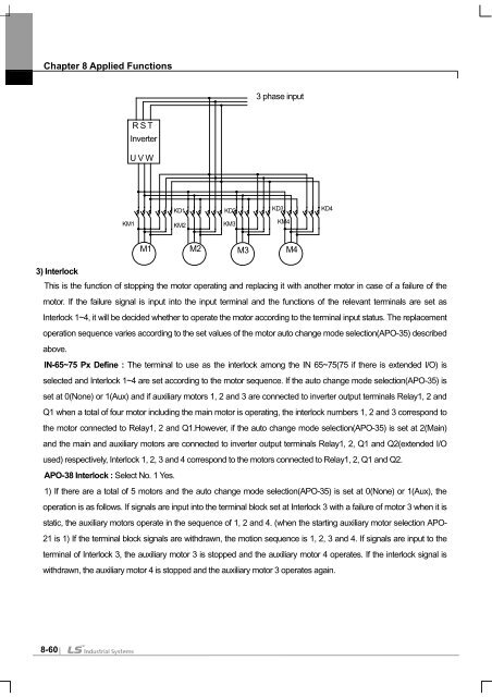
- Page 175: Chapter 8 Applied Functions APO-41
- Page 179 and 180: Chapter 8 Applied Functions ADV-75
- Page 181 and 182: Chapter 9 Monitor Functions 9-2 Set
- Page 183 and 184: Chapter 9 Monitor Functions * Warni
- Page 185 and 186: Chapter 9 Monitor Functions 2) Fail
- Page 187 and 188: Chapter 9 Monitor Functions 9-8 Set
- Page 189 and 190: Chapter 9 Monitor Functions 9.1.4 S
- Page 191 and 192: Chapter 9 Monitor Functions 4 : FDT
- Page 193 and 194: Chapter 9 Monitor Functions Functio
- Page 195 and 196: Chapter 9 Monitor Functions 9.1.5 F
- Page 197 and 198: Chapter 9 Monitor Functions CNF-71
- Page 199 and 200: Chapter 10 Protective Functions PRT
- Page 201 and 202: Chapter 10 Protective Functions PRT
- Page 203 and 204: 10.1.4 Motor overheat sensor input
- Page 205 and 206: Setting Items Functions bit2 bit1 O
- Page 207 and 208: 1) Speed Command Loss Chapter 10 Pr
- Page 209 and 210: T _ dec Example 1) % ED = × 100[%]
- Page 211 and 212: 10.1.12 Speed variation failure Thi
- Page 213 and 214: 10.1.19 Detection of motor not conn
- Page 215 and 216: Category Loader Display Description
- Page 217 and 218: Chapter 11 Communication Function 1
- Page 219 and 220: Chapter 11 Communication Function 1
- Page 221 and 222: Chapter 11 Communication Function C
- Page 223 and 224: Chapter 11 Communication Function 1
- Page 225 and 226: Chapter 11 Communication Function 1
- Page 227 and 228:
Chapter 11 Communication Function M
- Page 229 and 230:
Chapter 11 Communication Function F
- Page 231 and 232:
Chapter 11 Communication Function 1
- Page 233 and 234:
Chapter 11 Communication Function A
- Page 235 and 236:
Chapter 11 Communication Function A
- Page 237 and 238:
Chapter 11 Communication Function A
- Page 239 and 240:
Chapter 11 Communication Function A
- Page 241 and 242:
Chapter 11 Communication Function 2
- Page 243 and 244:
Chapter 11 Communication Function A
- Page 245 and 246:
Chapter 12 Checking and Troubleshoo
- Page 247 and 248:
12.1.3 Troubleshooting Chapter 12 C
- Page 249 and 250:
12.1.4 Replacement of cooling fan C
- Page 251 and 252:
12.1.5 Daily and regular checkup li
- Page 253 and 254:
Chapter 13 Table of Functions 13.1
- Page 255 and 256:
Chapter 13 Table of Functions 13.1.
- Page 257 and 258:
Chapter 13 Table of Functions 13-5
- Page 259 and 260:
Chapter 13 Table of Functions 13.1.
- Page 261 and 262:
Chapter 13 Table of Functions Exten
- Page 263 and 264:
Chapter 13 Table of Functions 13.1.
- Page 265 and 266:
Chapter 13 Table of Functions Contr
- Page 267 and 268:
Chapter 13 Table of Functions Contr
- Page 269 and 270:
Chapter 13 Table of Functions Input
- Page 271 and 272:
Chapter 13 Table of Functions Input
- Page 273 and 274:
Chapter 13 Table of Functions Input
- Page 275 and 276:
Chapter 13 Table of Functions Input
- Page 277 and 278:
Chapter 13 Table of Functions Commu
- Page 279 and 280:
Chapter 13 Table of Functions 3.1.8
- Page 281 and 282:
Chapter 13 Table of Functions No. 1
- Page 283 and 284:
Chapter 13 Table of Functions No. 1
- Page 285 and 286:
Chapter 13 Table of Functions 13.1.
- Page 287 and 288:
Chapter 13 Table of Functions No. C
- Page 289 and 290:
Chapter 13 Table of Functions No. 1
- Page 291 and 292:
Chapter 13 Table of Functions 3.1.1
- Page 293 and 294:
Chapter 13 Table of Functions 13-41
- Page 295 and 296:
ⅱ
- Page 297 and 298:
�����������
- Page 299:
Revision History No Date Edition Ve


