- Page 1 and 2:
Revit Structure 2009 Metric Tutoria
- Page 3:
copyright owner or contributors of
- Page 6 and 7:
Modifying Snap Settings . . . . . .
- Page 8 and 9:
Annotating . . . . . . . . . . . .
- Page 10 and 11:
Adding Slope Arrows to a Shed Roof
- Page 12 and 13:
The Contents tab of the Revit Struc
- Page 14 and 15:
10 In the left pane of the Choose T
- Page 16 and 17:
Understanding Autodesk Revit Struct
- Page 18 and 19:
The Menu Bar The Toolbar By default
- Page 20 and 21:
The Design Bar is located on the le
- Page 22 and 23:
You can use the Project Browser to
- Page 24 and 25:
18 On the Design Bar, click Modify.
- Page 26 and 27:
5 Click Zoom Out (2x). In the drawi
- Page 28 and 29:
End a command 18 On the Undo menu,
- Page 30 and 31:
Creating a New Project In this firs
- Page 32 and 33:
2 Click File menu ➤ Import/Link
- Page 34 and 35:
Adding Column Grids In this exercis
- Page 36 and 37:
13 Select the next grid line below
- Page 38 and 39:
Training File Continue to use the p
- Page 40 and 41:
11 Using the same method, place a c
- Page 42 and 43:
7 Drag the wall towards the left ed
- Page 44 and 45:
34 | Chapter 2 Express Workshops
- Page 46 and 47:
Notice the completed structural wal
- Page 48 and 49:
9 Sketch lines along the drawing pe
- Page 50 and 51:
9 On the Design Bar, click Symbolic
- Page 52 and 53:
17 Click File menu ➤ Save. 18 Pro
- Page 54 and 55:
Adding Foundations 13 Click File me
- Page 56 and 57:
NOTE The individual isolated founda
- Page 58 and 59:
View rebar in 3D 4 Enter ZF (Zoom t
- Page 60 and 61:
Footing reinforcement detail Column
- Page 62 and 63:
Notice that the area reinforcement
- Page 64 and 65:
Add a break line 54 | Chapter 2 Exp
- Page 66 and 67:
18 On the Design Bar, click Modify.
- Page 68 and 69:
25 On the Design Bar, click Modify.
- Page 70 and 71:
Copy the rebar 13 On the Design Bar
- Page 72 and 73:
22 Click to place the rebar. 23 Wit
- Page 74 and 75:
3 On the Options Bar, click (Edit C
- Page 76 and 77:
10 On the Design Bar, click Modify.
- Page 78 and 79:
■ On the View Control Bar, for Mo
- Page 80 and 81:
Importing/Linking a DWG File In thi
- Page 83 and 84:
Modifying Project and System Settin
- Page 85 and 86:
27 Click Settings menu ➤ Options.
- Page 87 and 88:
13 Navigate to C:\My Documents or a
- Page 89 and 90:
Modifying Snap Settings 25 Proceed
- Page 91 and 92:
16 Place the cursor over the horizo
- Page 93 and 94:
All of the exterior walls of this p
- Page 95 and 96:
TIP Typically, your training files
- Page 97 and 98:
3 On the View Control Bar, click Mo
- Page 99 and 100:
11 Click View menu ➤ Visibility/G
- Page 101 and 102:
27 On the View Toolbar, click . Not
- Page 103 and 104:
23 Click File menu ➤ Save. 24 Pro
- Page 105 and 106:
■ Completed Structure w/ Roof&Flo
- Page 107 and 108:
7 Click View menu ➤ Zoom ➤ Zoom
- Page 109 and 110:
The Perspective Line Weights tab co
- Page 111 and 112:
NOTE You cannot select specific sca
- Page 113 and 114:
Settings Menu Command Structural Se
- Page 115 and 116:
Modifying Views and View Templates
- Page 117 and 118:
29 To create additional 3D views, c
- Page 119 and 120:
3 Under General, enter the desired
- Page 121 and 122:
In this exercise, detailed instruct
- Page 123 and 124:
3 Under Settings, click Setup. 4 Cl
- Page 125 and 126:
Starting a New Project In this tuto
- Page 127 and 128:
The halftone of the imported drawin
- Page 129 and 130:
The halftone of the imported drawin
- Page 131 and 132:
Set options Exterior facade outline
- Page 133 and 134:
Copying levels NOTE If you are prom
- Page 135 and 136:
Manage links 27 In the Element Prop
- Page 137 and 138:
Creating a Structural Model In this
- Page 139 and 140:
As you select subsequent grid lines
- Page 141 and 142:
20 Click the column to select the a
- Page 143 and 144:
25 Click File menu ➤ Close. To sa
- Page 145 and 146:
7 Press ESC. Notice that columns ar
- Page 147 and 148:
Adding Horizontal Framing In this e
- Page 149 and 150:
NOTE If necessary, you can select t
- Page 151 and 152:
12 On the Design Bar, click Finish
- Page 153 and 154:
Automatically create a beam system
- Page 155 and 156:
Beam system displays with dashed li
- Page 157 and 158:
Revit Structure provides a deck spa
- Page 159 and 160:
■ Enter SM (keyboard shortcut for
- Page 161 and 162:
3 On the Modelling tab of the Desig
- Page 163 and 164:
5 In the Filter dialog, do the foll
- Page 165 and 166:
NOTE Although you previously added
- Page 167 and 168:
Specify the top of steel 11 On the
- Page 169 and 170:
27 Select the beam that spans the m
- Page 171 and 172:
3 On the Modelling tab of the Desig
- Page 173 and 174:
■ In the left pane of the Open di
- Page 175 and 176:
Adding Shafts 11 Proceed to the nex
- Page 177 and 178:
Duplicating Framing 18 Click File m
- Page 179 and 180:
13 On the Design Bar, click Finish
- Page 181 and 182:
33 In the Filter dialog, click Chec
- Page 183 and 184:
5 On the Basics tab of the Design B
- Page 185 and 186:
Edit the slab 22 In the Project Bro
- Page 187 and 188:
The corner points of the slab are h
- Page 189 and 190:
Each line will be extended and trim
- Page 191 and 192:
59 On the Design Bar, click Modify.
- Page 193 and 194:
Sketch split lines 3 Select the atr
- Page 195 and 196:
Place additional points Delete spli
- Page 197 and 198:
View section view of slab 18 In the
- Page 199 and 200:
31 On the Design Bar, click Modify.
- Page 201 and 202:
Add the miter join 3 On the View Co
- Page 203 and 204:
The miter join is complete. 9 Click
- Page 205 and 206:
Notice the miter lock remains locke
- Page 207 and 208:
8 Click the grid line so the beam s
- Page 209 and 210:
14 In the Element Properties dialog
- Page 211 and 212:
Approximate the curve of the analyt
- Page 213 and 214:
3 On the Architectural tab of the D
- Page 215 and 216:
15 Click File menu ➤ Close. To sa
- Page 217 and 218:
Change the stiffener plate properti
- Page 219 and 220:
14 On the Family Design Bar, click
- Page 221 and 222:
30 Navigate to a folder of your pre
- Page 223 and 224:
Sketch the atrium walls 1 In the Pr
- Page 225 and 226:
Adding Piers or Pilasters To save c
- Page 227 and 228:
6 Select the exterior face of the f
- Page 229 and 230:
Copy the framing and slab to Garage
- Page 231 and 232:
Completed ramp Add a sloped beam sy
- Page 233 and 234:
NOTE Depending on where you draw th
- Page 235 and 236:
15 On the Design Bar, click Modify.
- Page 237 and 238:
Precast Concrete In this tutorial,
- Page 239 and 240:
9 Proceed to the next exercise, Cha
- Page 241 and 242:
4 On the Options Bar, click . 5 In
- Page 243 and 244:
Open the beam profile 6 In the Fami
- Page 245 and 246:
22 Press ESC. 23 Click the referenc
- Page 247 and 248:
37 Enter AL (this is the keyboard s
- Page 249 and 250:
Modify the right tee of the beam 49
- Page 251 and 252:
Creating Drawings In this tutorial,
- Page 253 and 254:
NOTE The Project Path parameter in
- Page 255 and 256:
NOTE If necessary, you can select t
- Page 257 and 258:
NOTE This exercise requires the com
- Page 259 and 260:
15 On the View Toolbar, click , and
- Page 261 and 262:
Notice there are 3 typical detail v
- Page 263 and 264:
Importing Details from the Library
- Page 265 and 266:
■ Click OK. Because you are impor
- Page 267 and 268:
■ Click Open. 11 In the Insert Vi
- Page 269 and 270:
NOTE This exercise requires the com
- Page 271 and 272:
15 Working from the top down, enter
- Page 273 and 274:
Scheduling In this tutorial, you le
- Page 275 and 276:
10 Click File menu ➤ Close. To sa
- Page 277 and 278:
■ Under Type of Parameter, select
- Page 279 and 280:
Select a filter Format units A new
- Page 281 and 282:
23 In the Schedule Properties dialo
- Page 283 and 284:
Customizing the Type Schedule In th
- Page 285 and 286:
9 While pressing CTRL, select multi
- Page 287 and 288:
■ Click OK. 17 In the Element Pro
- Page 289 and 290:
Group rebar columns Enter rebar dat
- Page 291 and 292:
NOTE The cost value represents a ra
- Page 293 and 294:
2 Right-click the column schedule,
- Page 295 and 296:
■ In the Element Properties dialo
- Page 297 and 298:
7 Click OK. 8 In the Element Proper
- Page 299 and 300:
Split the column schedule 21 Right-
- Page 301 and 302:
Add additional sheets The first seg
- Page 303 and 304:
tables. For example, instance table
- Page 305 and 306:
Steel Details In this tutorial, you
- Page 307 and 308:
9 Draw a section as shown. 10 On th
- Page 309 and 310:
Detailing Steel 32 Click File menu
- Page 311 and 312:
Next, you create 2 detail lines tha
- Page 313 and 314:
18 Select the middle vertical line
- Page 315 and 316:
Label the angles and the plate 29 O
- Page 317 and 318:
7 On the Options Bar, click . 8 Ent
- Page 319 and 320:
9 Next, select the back of the chan
- Page 321 and 322:
Creating a Deck Span Transition Det
- Page 323 and 324:
25 On the Design bar, click Modify.
- Page 325 and 326:
Concrete Reinforcement Modelling In
- Page 327 and 328:
NOTE You can open or close the Reba
- Page 329 and 330:
18 Pace a single rebar at the botto
- Page 331 and 332:
Notice that the rebar sets are visi
- Page 333 and 334:
Reinforcement in a Column In this e
- Page 335 and 336:
10 On the Design Bar, click Modify.
- Page 337 and 338:
View rebar in 3D 22 On the Options
- Page 339 and 340:
■ In the left pane of the Open di
- Page 341 and 342:
10 Use the ViewCube to rotate the m
- Page 343 and 344:
Remove the major bars The area rein
- Page 345 and 346:
Notice the rebar for the major span
- Page 347 and 348:
29 Click File menu ➤ Close. To sa
- Page 349 and 350:
Sketch the area reinforcement 8 In
- Page 351 and 352:
The area reinforcement for the slab
- Page 353 and 354:
Change bar type 5 On the Options Ba
- Page 355 and 356:
NOTE The line weights in your file
- Page 357 and 358:
4 Press ESC. 5 Double-click the sec
- Page 359 and 360:
Sketch rebar parallel to the footin
- Page 361 and 362:
Mirror the rebar 27 On the Options
- Page 363 and 364:
39 On the Design Bar, click Modify.
- Page 365 and 366:
48 On the Options Bar, click . 49 O
- Page 367 and 368:
To save changes, click File menu
- Page 369 and 370:
Place horizontal rebar ■ Click Mo
- Page 371 and 372:
20 On the Design Bar, click Modify.
- Page 373 and 374:
31 Drag the sketch line up towards
- Page 375 and 376:
40 Press CTRL, and select the outsi
- Page 377 and 378:
47 On the Toolbar, click , and draw
- Page 379 and 380:
Annotating and Dimensioning In this
- Page 381 and 382:
8 On the Design Bar, click Modify.
- Page 383 and 384:
Create a linear dimension 29 On the
- Page 385 and 386:
46 In the Element Properties dialog
- Page 387 and 388:
Edit dimension witness lines 12 On
- Page 389 and 390:
20 To end the editing command, clic
- Page 391 and 392:
position, while the second componen
- Page 393 and 394:
Align the windows on the floor plan
- Page 395 and 396:
2 On the Design Bar, click Dimensio
- Page 397 and 398:
■ Move the cursor up and to the l
- Page 399 and 400:
16 On the Options Bar, select Leade
- Page 401 and 402:
Add spot coordinates to a sloped be
- Page 403 and 404:
Tag all beams in plan view 1 In the
- Page 405 and 406:
■ In the Beam Annotations dialog,
- Page 407 and 408:
24 In the Edit Label dialog, under
- Page 409 and 410:
■ Click OK. 35 In the Type Select
- Page 411 and 412:
Align the beam tag ■ Under Catego
- Page 413 and 414:
■ Click OK. 21 Click File ➤ Sav
- Page 415 and 416:
Worksets On many building projects,
- Page 417 and 418:
8 In the Worksets dialog, click New
- Page 419 and 420:
You have created the required works
- Page 421 and 422:
In this exercise, you enabled Works
- Page 423 and 424:
All structural columns in the model
- Page 425 and 426:
In the Worksets dialog, notice User
- Page 427 and 428:
Assign the roof workset 13 Select t
- Page 429 and 430:
25 In the Save to Central dialog, s
- Page 431 and 432:
A warning is displayed informing yo
- Page 433 and 434:
42 Click File menu ➤ Save to Cent
- Page 435 and 436:
14 In the Editing Requests dialog,
- Page 437 and 438:
Project Coordination You have recei
- Page 439 and 440:
10 On the Toolbar, click , and draw
- Page 441 and 442:
Review location of grid B The concr
- Page 443 and 444:
Review wall modifications The eleva
- Page 445 and 446:
Notice the categories for the archi
- Page 447 and 448:
There are 7 instances of interferen
- Page 449 and 450:
12 In the Interference Report dialo
- Page 451 and 452:
If Visible is not selected, any rev
- Page 453 and 454:
If Visible is not selected, any rev
- Page 455 and 456:
23 On the Design Bar, click Finish
- Page 457 and 458:
The Activate View command activates
- Page 459 and 460:
8 Proceed to the next tutorial, Str
- Page 461 and 462:
Structural Analytical Modelling 14
- Page 463 and 464:
NOTE If the visibility of loads is
- Page 465 and 466:
The unsupported element is highligh
- Page 467 and 468:
Run a consistency check Review warn
- Page 469 and 470:
9 In the Element Properties dialog,
- Page 471 and 472:
The first table is the Load Cases t
- Page 473 and 474:
2 On the View Control Bar, click th
- Page 475 and 476:
TIP Be sure to click the Area Load
- Page 477 and 478:
■ Select WIND1(3) for Load Case,
- Page 479 and 480:
This grid is drawn for reference on
- Page 481 and 482:
Load Combination 36 Click File menu
- Page 483 and 484:
26 In the Structural Settings dialo
- Page 485 and 486:
The load combinations are displayed
- Page 487 and 488:
Create a load schedule Define the f
- Page 489 and 490:
3 Click Tools menu ➤ Analytical M
- Page 491 and 492:
Aligns the vertical and horizontal
- Page 493 and 494:
Adjust the beam to slab vertical of
- Page 495 and 496:
The vertical projection plane of th
- Page 497 and 498:
19 Double-click the section bubble
- Page 499 and 500:
The vertical projection plane for t
- Page 501 and 502:
The brown line represents the analy
- Page 503 and 504:
The horizontal projection plane of
- Page 505 and 506:
53 Click the beam, and on the Optio
- Page 507 and 508:
Boundary Conditions In this exercis
- Page 509 and 510:
Notice the boundary condition now d
- Page 511 and 512:
Exporting Revit Structure Files You
- Page 513 and 514:
■ Under Prefer, select AutoCAD Ar
- Page 515 and 516:
Exporting a 2D view to AutoCAD Trai
- Page 517 and 518:
Export sheets 1 Click File menu ➤
- Page 519 and 520:
When the sheets are opened in AutoC
- Page 521 and 522:
About Families and the Family Edito
- Page 523 and 524:
The following illustration shows ho
- Page 525 and 526:
General procedure for creating a st
- Page 527 and 528:
Creating Components in the Family E
- Page 529 and 530:
Modify the angular reference plane
- Page 531 and 532:
18 Select the dimension that refers
- Page 533 and 534:
The dimensions displayed in the fol
- Page 535 and 536:
43 Select the upper dovetail dimens
- Page 537 and 538:
Create a new project 59 Click File
- Page 539 and 540:
83 Proceed to the next exercise, Cu
- Page 541 and 542:
Notice the opening in the beam chan
- Page 543 and 544:
Place dimensions 6 On the Design Ba
- Page 545 and 546:
15 On the Options Bar, for Label, s
- Page 547 and 548:
Launch the rebar shape browser 36 O
- Page 549 and 550:
46 On the Design Bar, click Modify.
- Page 551 and 552:
Sketch the extrusion Make sure the
- Page 553 and 554:
27 Click to place a third copy of t
- Page 555 and 556:
Join extrusion elements to each oth
- Page 557 and 558:
The titleblock has linework, text,
- Page 559 and 560:
18 On the Options Bar, click , and
- Page 561 and 562: Create a new 10mm text style 5 On t
- Page 563 and 564: 26 Move the cursor down 120mm, and
- Page 565 and 566: Add drawing data labels 40 On the D
- Page 567 and 568: 55 Click OK twice. Add sheet number
- Page 569 and 570: Adding the Titleblock to a New Proj
- Page 571 and 572: Truss Building In this tutorial, yo
- Page 573 and 574: The truss is placed between the col
- Page 575 and 576: 21 Enter ZF (keyboard shortcut for
- Page 577 and 578: 35 Click the top endpoint of the co
- Page 579 and 580: Modify each truss 40 On the View to
- Page 581 and 582: 8 In the Element Properties dialog,
- Page 583 and 584: NOTE Check the Status Bar to make s
- Page 585 and 586: Attach the roof 3 Click Edit menu
- Page 587 and 588: Creating a Custom Truss Family In t
- Page 589 and 590: 14 Click the intersection of the bo
- Page 591 and 592: 27 In the Project Browser, under 3D
- Page 593 and 594: Add framing elevations 8 On the Bas
- Page 595 and 596: 24 On the Tools toolbar, click . 25
- Page 597 and 598: 36 On the Design Bar, click Ref Pla
- Page 599 and 600: The completed truss is displayed. 4
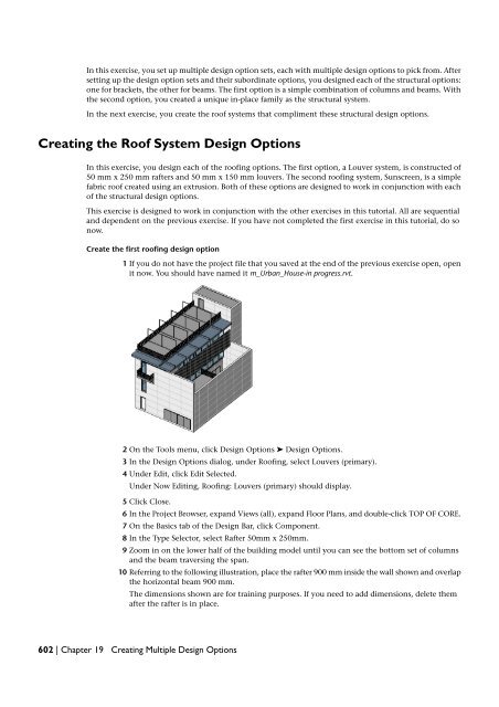
- Page 601 and 602: Creating Multiple Design Options Wh
- Page 603 and 604: 4 In the Project Browser, expand Vi
- Page 605 and 606: Notice the 12 columns that you adde
- Page 607 and 608: Notice that the beams complete the
- Page 609 and 610: 55 On the Basics tab of the Design
- Page 611: Three more roof beams are placed at
- Page 615 and 616: Add the louvers to the design optio
- Page 617 and 618: The louver roof system is complete.
- Page 619 and 620: The louver roof system is complete.
- Page 621 and 622: 14 In the Project Browser, under Vi
- Page 623 and 624: Linking Building Models and Sharing
- Page 625 and 626: ■ Auto - Origin to Origin: The or
- Page 627 and 628: The condo complex building model is
- Page 629 and 630: Rotate the townhouse The townhouse
- Page 631 and 632: Copy the townhouse The townhouse is
- Page 633 and 634: 38 On the File menu, click Save. NO
- Page 635 and 636: Notice that the townhouse is now at
- Page 637 and 638: Apply halftone 12 Using the same te
- Page 639 and 640: NOTE This exercise requires the com
- Page 641 and 642: 10 In the Save As dialog, navigate
- Page 643 and 644: 4 In the Manage Place and Locations
- Page 645 and 646: Save locations Notice the OK button
- Page 647 and 648: Working with a Linked Building Mode
- Page 649 and 650: 7 Click View menu ➤ Zoom ➤ Zoom
- Page 651 and 652: 8 Click OK. Sort schedule data In o
- Page 653 and 654: Project Phasing In any project, you
- Page 655 and 656: Phase 2 (north) After you add phase
- Page 657 and 658: In the Element Properties dialog, n
- Page 659 and 660: 23 Use a crossing window to select
- Page 661 and 662: to determine which phase is shown a
- Page 663 and 664:
Apply the Demo Red graphic override
- Page 665 and 666:
Dataset ■ Click File menu ➤ Ope
- Page 667 and 668:
20 In the Project Browser, expand F
- Page 669 and 670:
Rendering Views and Creating Walkth
- Page 671 and 672:
Training File ■ Click File menu
- Page 673 and 674:
11 In the Render Appearance Library
- Page 675 and 676:
32 Click Settings menu ➤ Object S
- Page 677 and 678:
42 Specify options in the Rendering
- Page 679 and 680:
3 On the Site tab of the Design Bar
- Page 681 and 682:
15 On the Design Bar, click Modify.
- Page 683 and 684:
3 Zoom out, and select the crop bou
- Page 685 and 686:
Creating the Exterior Rendering In
- Page 687 and 688:
9 In the Rendering dialog, click Sh
- Page 689 and 690:
Adjust the exposure 28 In the Rende
- Page 691 and 692:
Add an RPC figure to the view 1 In
- Page 693 and 694:
15 Proceed to the next exercise, Cr
- Page 695 and 696:
7 Click Window menu ➤ Close Hidde
- Page 697 and 698:
15 Maximize the 3D view, and adjust
- Page 699 and 700:
9 Close the Rendering dialog. Creat
- Page 701 and 702:
22 In the Element Properties dialog
- Page 703 and 704:
■ Shading with Edges ■ Renderin
- Page 705 and 706:
8 Verify that the crop boundary of
- Page 707 and 708:
5 Select the target point of the ca
- Page 709 and 710:
Roofs In this tutorial, you learn h
- Page 711 and 712:
9 Sketch a similar reference plane
- Page 713 and 714:
Notice that the breezeway roof pene
- Page 715 and 716:
You begin by sketching the perimete
- Page 717 and 718:
Creating a Roof with a Vertical Pen
- Page 719 and 720:
18 On the View toolbar, click (Defa
- Page 721 and 722:
12 Repeat the trim procedure on the
- Page 723 and 724:
Creating a Shed Roof from a Footpri
- Page 725 and 726:
2 Select the shed roof over the ent
- Page 727 and 728:
4 Select the two gable end lines (t
- Page 729 and 730:
6 On the View toolbar, click (Defau
- Page 731 and 732:
Create a flat roof by footprint 1 I
- Page 733 and 734:
Open a section view 12 In the drawi
- Page 735 and 736:
Add elevation points The roof is no
- Page 737 and 738:
27 Press and hold CTRL, and select
- Page 739 and 740:
Creating Roof Fascia In this exerci
- Page 741 and 742:
3 In the Properties dialog, click E
- Page 743 and 744:
4 Select the roof. 5 On the Design
- Page 745 and 746:
Grouping Using the grouping functio
- Page 747 and 748:
3 Draw a selection box (lower-right
- Page 749 and 750:
Place instances of the group 9 In t
- Page 751 and 752:
17 Select the kitchen in the stairw
- Page 753 and 754:
Save the training file Modifying a
- Page 755 and 756:
Add elements for a unique condition
- Page 757 and 758:
Nesting Groups 25 On the Design Bar
- Page 759 and 760:
6 Press TAB, select the wall betwee
- Page 761 and 762:
3 On the Drafting tab of the Design
- Page 763 and 764:
18 On the Design Bar, click Modify.
- Page 765 and 766:
7 On the Options Bar, click (Filter
- Page 767 and 768:
Continue using the training file sa