

The Gougeon Brothers on Boat Construction - WEST SYSTEM Epoxy
The Gougeon Brothers on Boat Construction - WEST SYSTEM Epoxy
The Gougeon Brothers on Boat Construction - WEST SYSTEM Epoxy

Create successful ePaper yourself
Turn your PDF publications into a flip-book with our unique Google optimized e-Paper software.
Chapter 12 – Scarfing 115<br />
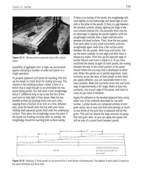
Figure 12-11 Planing narrow plywood strips with a block<br />
plane.<br />
possibility of aggregate error is high, we recommend<br />
against clamping a number of wide scarf joints in a<br />
single operati<strong>on</strong>.<br />
To prepare plywood scarf joints for b<strong>on</strong>ding, first line<br />
up the bevels to check them for mating accuracy. This<br />
requires a flat working surface—either a floor or a<br />
bench that is large enough to accommodate the two<br />
pieces being joined. You will need a steel straightedge<br />
about 1' (300mm) l<strong>on</strong>g to lay across the face of the<br />
scarf joint to help sight it from above. Mate the two<br />
beveled surfaces by pushing them into each other,<br />
tapping them a fracti<strong>on</strong> of an inch at a time. Between<br />
taps, press the bevels from the top with your hand,<br />
holding both plywood panels flush with the underlying<br />
surface. <str<strong>on</strong>g>The</str<strong>on</strong>g>n place the straightedge across the joint; if<br />
the bevels are meeting correctly with no overlap, the<br />
straightedge should be touching both surfaces evenly.<br />
2"<br />
2"<br />
Bench<br />
2"<br />
If there is an overlap of the bevels, the straightedge will<br />
rock slightly <strong>on</strong> the featheredge and stand high <strong>on</strong> <strong>on</strong>e<br />
side or the other of the panels. If there is a gap between<br />
the beveled surfaces, simply sighting the edge of the<br />
scarf should indicate this. Occasi<strong>on</strong>ally there may be<br />
an advantage in tapping the panels together until the<br />
straightedge indicates that a slight override exists<br />
between the bevel surfaces. <str<strong>on</strong>g>The</str<strong>on</strong>g>n, draw the two panels<br />
from each other in very small increments until the<br />
straightedge again reads that a flat surface exists<br />
between the two panels. With l<strong>on</strong>g scarf joints, line<br />
up the bevel carefully <strong>on</strong> <strong>on</strong>e edge and then insert a<br />
temporary staple. <str<strong>on</strong>g>The</str<strong>on</strong>g>n line up the opposite edge in<br />
similar fashi<strong>on</strong> and insert a staple in it. If you have<br />
machined the bevels straight <strong>on</strong> both panels, the mating<br />
between the two in the center porti<strong>on</strong> of the panel<br />
should follow the accuracy that is developed at either<br />
end. When the panels are in perfect alignment, make<br />
surmarks across the faces of both panels so that when<br />
you apply adhesive, you can reassemble them in the<br />
exact positi<strong>on</strong>. Make the surmarks across the scarf joint<br />
edge at approximately a 45° angle. Make at least two<br />
surmarks, <strong>on</strong>e at each edge of the panel, and insert as<br />
many as you need in between.<br />
Apply the adhesive to the beveled plywood faces using<br />
either <strong>on</strong>e of the methods described for use with<br />
lumber. Lumber bevels are composed entirely of endgrain<br />
wood, but at least <strong>on</strong>e third and perhaps as much<br />
as two thirds of the joint face of plywood will be flat<br />
grain. This will not absorb the large amounts of epoxy<br />
that end grain does, so you can apply less epoxy and<br />
still be sure of a sound b<strong>on</strong>d between panels.<br />
Clamps should be placed<br />
as close as possible to<br />
the scarf.<br />
Figure 12-12 Stacking 1 ⁄4" thick panels to cut several 8-to-1 scarf bevels simultaneously. <str<strong>on</strong>g>The</str<strong>on</strong>g> setback of each panel is based <strong>on</strong><br />
the panel thickness and bevel ratio.<br />
1 ⁄4"<br />
2"


