

The Gougeon Brothers on Boat Construction - WEST SYSTEM Epoxy
The Gougeon Brothers on Boat Construction - WEST SYSTEM Epoxy
The Gougeon Brothers on Boat Construction - WEST SYSTEM Epoxy

Create successful ePaper yourself
Turn your PDF publications into a flip-book with our unique Google optimized e-Paper software.
282 Hull C<strong>on</strong>structi<strong>on</strong> Methods<br />
and after c<strong>on</strong>structi<strong>on</strong>, encapsulating the wood to stabilize<br />
its moisture c<strong>on</strong>tent and to protect it from the<br />
harmful effects of moisture. We can produce very light,<br />
stiff, str<strong>on</strong>g, and l<strong>on</strong>g-lived hulls by using the b<strong>on</strong>ding<br />
and sealing qualities of <strong>WEST</strong> <strong>SYSTEM</strong> epoxy in combinati<strong>on</strong><br />
with good plywood and lumber.<br />
Best of all, sheet plywood is probably the easiest and<br />
fastest material to work with when building a hard chine<br />
hull. <str<strong>on</strong>g>The</str<strong>on</strong>g>re are a number of reas<strong>on</strong>s for this. For instance,<br />
the lofting of a hard chine boat is greatly simplified<br />
because most of its surface area is in a <strong>on</strong>e-dimensi<strong>on</strong>al<br />
plane. When lofting a hull that has compound curvature,<br />
you must define all points <strong>on</strong> its surface; with a<br />
hard chine hull, you <strong>on</strong>ly need to define the locati<strong>on</strong> of<br />
the chine, keel, and sheer points <strong>on</strong> the lofting board.<br />
This simplifies and greatly speeds up the lofting process<br />
and enables you to develop a body plan in a fracti<strong>on</strong> of<br />
the time normally required for a typical rounded-hull<br />
shape. In additi<strong>on</strong>, the time needed to mark, cut, and<br />
assemble mold frames or permanent frames is greatly<br />
reduced because the process is much easier.<br />
Frame Assembly<br />
In other boatbuilding methods, mold frames are removed<br />
when the hull is finished. In hard chine c<strong>on</strong>structi<strong>on</strong>,<br />
however, most frames stay permanently in the boat<br />
because the flat planes of plywood hulls usually require<br />
the support of substantial framework for adequate stiffness.<br />
Although frames can be made of plywood, the<br />
straight secti<strong>on</strong>s of hard chine hulls often make straight<br />
stock a better choice structurally and ec<strong>on</strong>omically.<br />
Usually, we decide early in the project <strong>on</strong> a standard<br />
size of frame material—1" � 3" (19mm � 63mm)<br />
stock is typical. Two main factors that determine the<br />
size of the frame material are the weight and size of the<br />
boat, and the dimensi<strong>on</strong>s of the stringers and chines<br />
that will be notched into the frames. A notched frame<br />
must retain adequate load-bearing capacity. For example,<br />
if you are going to set 11 ⁄2" � 3 ⁄4" (36mm � 18mm)<br />
stringers <strong>on</strong> edge into 3" � 3 ⁄4" (75mm � 18mm) frames,<br />
you can <strong>on</strong>ly count <strong>on</strong> 11 ⁄2" of the frame material to be<br />
load-bearing until the outer skin is applied. You will<br />
have to decide whether the 11 ⁄2" of unnotched frame<br />
stock is adequate for your particular situati<strong>on</strong>.<br />
After you have decided <strong>on</strong> a standard dimensi<strong>on</strong> for the<br />
frame material, prepare enough of the desired stock to<br />
make all of the frames in the boat. In many cases, you<br />
can save time by rounding over (or “radiusing”) what<br />
will be the interior edge and then sanding and<br />
precoating all of the frame stock before it is sawn and<br />
assembled into frames. In some cases, however, it may<br />
be easier to perform these finishing operati<strong>on</strong>s after you<br />
have assembled the frames.<br />
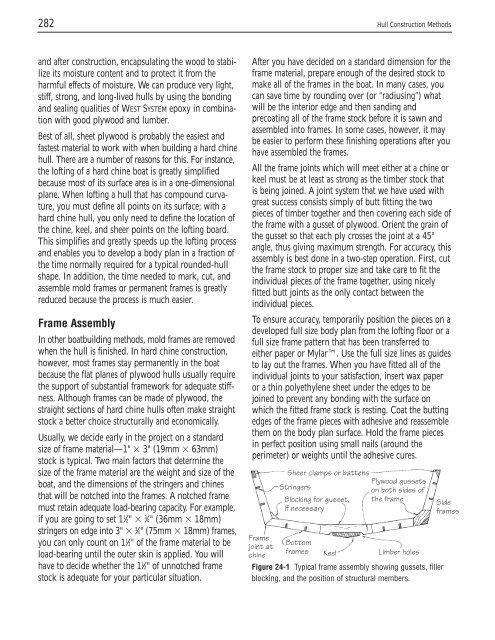
All the frame joints which will meet either at a chine or<br />
keel must be at least as str<strong>on</strong>g as the timber stock that<br />
is being joined. A joint system that we have used with<br />
great success c<strong>on</strong>sists simply of butt fitting the two<br />
pieces of timber together and then covering each side of<br />
the frame with a gusset of plywood. Orient the grain of<br />
the gusset so that each ply crosses the joint at a 45°<br />
angle, thus giving maximum strength. For accuracy, this<br />
assembly is best d<strong>on</strong>e in a two-step operati<strong>on</strong>. First, cut<br />
the frame stock to proper size and take care to fit the<br />
individual pieces of the frame together, using nicely<br />
fitted butt joints as the <strong>on</strong>ly c<strong>on</strong>tact between the<br />
individual pieces.<br />
To ensure accuracy, temporarily positi<strong>on</strong> the pieces <strong>on</strong> a<br />
developed full size body plan from the lofting floor or a<br />
full size frame pattern that has been transferred to<br />
either paper or Mylar. Use the full size lines as guides<br />
to lay out the frames. When you have fitted all of the<br />
individual joints to your satisfacti<strong>on</strong>, insert wax paper<br />
or a thin polyethylene sheet under the edges to be<br />
joined to prevent any b<strong>on</strong>ding with the surface <strong>on</strong><br />
which the fitted frame stock is resting. Coat the butting<br />
edges of the frame pieces with adhesive and reassemble<br />
them <strong>on</strong> the body plan surface. Hold the frame pieces<br />
in perfect positi<strong>on</strong> using small nails (around the<br />
perimeter) or weights until the adhesive cures.<br />
Frame<br />
joint at<br />
chine<br />
Sheer clamps or battens<br />
Stringers<br />
Blocking for gusset,<br />
if necessary<br />
Plywood gussets<br />
<strong>on</strong> both sides of<br />
the frame<br />
Bottom<br />
frames Keel Limber holes<br />
Figure 24-1 Typical frame assembly showing gussets, filler<br />
blocking, and the positi<strong>on</strong> of structural members.<br />
Side<br />
frames


