

The Gougeon Brothers on Boat Construction - WEST SYSTEM Epoxy
The Gougeon Brothers on Boat Construction - WEST SYSTEM Epoxy
The Gougeon Brothers on Boat Construction - WEST SYSTEM Epoxy

Create successful ePaper yourself
Turn your PDF publications into a flip-book with our unique Google optimized e-Paper software.
Chapter 25 – Compounded Plywood C<strong>on</strong>structi<strong>on</strong> 313<br />
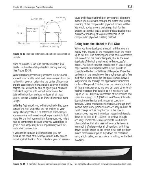
Block<br />
Secti<strong>on</strong> line<br />
Marking <strong>on</strong><br />
waterline<br />
Flat surface Model secured plumb<br />
and level <strong>on</strong> blocking<br />
Waterline<br />
Figure 25-33 Marking waterlines and stati<strong>on</strong> lines <strong>on</strong> fold-up<br />
models.<br />
plane as a guide. Make sure that the model is also<br />
parallel in the athwartship directi<strong>on</strong> during marking.<br />
(See Figure 25-33.)<br />
With waterlines permanently inscribed <strong>on</strong> the model,<br />
you will now be able to take off measurements from the<br />
hull so that you can determine the center of buoyancy<br />
and the total displacement available at given waterline<br />
heights. You will also be able to figure your prismatic<br />
coefficient together with wetted surface area. For<br />
detailed instructi<strong>on</strong>s <strong>on</strong> how to figure all of these<br />
factors, c<strong>on</strong>sult Chapter 23 of Skene’s Elements of Yacht<br />
Design.<br />
With this first model, you will undoubtedly find some<br />
parts of the hull shape that are not entirely to your<br />
liking. <str<strong>on</strong>g>The</str<strong>on</strong>g> object then is to determine what changes<br />
you can make in the next model to persuade it to look<br />
more like the hull you envisi<strong>on</strong>. Remember, you might<br />
have to compromise because what you would like to<br />
get in a hull shape may be an impossibility with this<br />
method of c<strong>on</strong>structi<strong>on</strong>.<br />
If you decide to make a sec<strong>on</strong>d model, you can<br />
measure the effect of the changes made in the sec<strong>on</strong>d<br />
model against the first. From this data, you can assess a<br />
cause and effect relati<strong>on</strong>ship of any change. <str<strong>on</strong>g>The</str<strong>on</strong>g> more<br />
models you build with changes, the better your understanding<br />
of the compounded plywood process will be.<br />
We would advise any<strong>on</strong>e designing a hull for this<br />
process to spend at least a couple of days developing a<br />
number of models just to gain experience in the<br />
compounded plywood building method.<br />
Going from the Model to Full Size<br />
When you have developed a model hull that you are<br />
happy with, expand all the measurements of the model<br />
up to full size. <str<strong>on</strong>g>The</str<strong>on</strong>g> most important set of measurements<br />
will come from the master template, that is, the exact<br />
duplicate of the hull panels used in the successful<br />
model. Positi<strong>on</strong> the master template <strong>on</strong> 1 ⁄4" square graph<br />
paper with the anticipated waterlines as parallel as<br />
possible to the horiz<strong>on</strong>tal lines of the paper. Draw the<br />
perimeter of the template <strong>on</strong> the graph paper using fine<br />
lead with a sharp point for the best accuracy. Draw a<br />
l<strong>on</strong>gitudinal line through the approximate horiz<strong>on</strong>tal<br />
center of the panel. This becomes the reference line for<br />
all future measurements, and you can draw other l<strong>on</strong>gitudinal<br />
reference lines parallel to it if necessary. (See<br />
Figure 25-35.) Make measurements of the keel line and<br />
sheer line using 1' to 2' (300mm to 600mm) intervals,<br />
depending <strong>on</strong> the size and amount of curvature<br />
involved. Closer measurement intervals, although they<br />
involve more work, produce more accuracy. In areas of<br />
rapid change such as might occur in the bow or<br />
transom, you may want to reduce measuring intervals<br />
down to as little as 4" (100mm) to achieve enough<br />
accuracy. Transfer these measurements to a full size<br />
plywood sheet that also uses a drawn centerline as a<br />
main point of reference for all dimensi<strong>on</strong>s, with lines<br />
drawn at right angles to the centerline at each predetermined<br />
measurement point. Lay down the centerline<br />
using a tight cable, just as is d<strong>on</strong>e in lofting, for the best<br />
accuracy.<br />
Figure 25-34 A model of the outriggers shown in Figure 25-27. This model has been marked with waterlines and secti<strong>on</strong> lines.


