

The Gougeon Brothers on Boat Construction - WEST SYSTEM Epoxy
The Gougeon Brothers on Boat Construction - WEST SYSTEM Epoxy
The Gougeon Brothers on Boat Construction - WEST SYSTEM Epoxy

You also want an ePaper? Increase the reach of your titles
YUMPU automatically turns print PDFs into web optimized ePapers that Google loves.
Chapter 16 – Lofting 183<br />
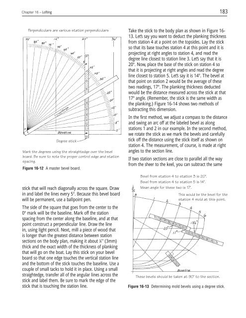
Perpendiculars are various stati<strong>on</strong> perpendiculars<br />
Degree stick<br />
Mark the degrees using the straightedge over the bevel<br />
board. Be sure to note the proper c<strong>on</strong>trol edge and stati<strong>on</strong><br />
spacing.<br />
Figure 16-12 A master bevel board.<br />
stick that will reach diag<strong>on</strong>ally across the square. Draw<br />
in and label the lines every 5°. Because this bevel board<br />
will be permanent, use a ballpoint pen.<br />
<str<strong>on</strong>g>The</str<strong>on</strong>g> side of the square that goes from the center to the<br />
0° mark will be the baseline. Mark off the stati<strong>on</strong><br />
spacing from the center al<strong>on</strong>g the baseline, and at that<br />
point c<strong>on</strong>struct a perpendicular line. Draw the line<br />
in, using light pencil. Next, mill a piece of wood that<br />
is l<strong>on</strong>ger than the greatest distance between stati<strong>on</strong><br />
secti<strong>on</strong>s <strong>on</strong> the body plan, making it about 1 ⁄8" (3mm)<br />
thick and the exact width of the thickness of planking<br />
that will go <strong>on</strong> the boat. Lay this stick <strong>on</strong> your bevel<br />
board so that <strong>on</strong>e edge touches the vertical stati<strong>on</strong> line<br />
and the bottom of the stick touches the baseline. Use a<br />
couple of small tacks to hold it in place. Using a small<br />
straightedge, transfer all of the angular lines across the<br />
stick and label them. Be sure to mark the edge of the<br />
stick that is touching the stati<strong>on</strong> line.<br />
Take the stick to the body plan as shown in Figure 16-<br />
13. Let’s say you want to deduct the planking thickness<br />
from stati<strong>on</strong> 4 at a point <strong>on</strong> the topsides. Lay the stick<br />
so that its base touches stati<strong>on</strong> 4 at this point and it is<br />
projecting at right angles to stati<strong>on</strong> 4, and read the<br />
degree line closest to stati<strong>on</strong> line 3. Let’s say that it is<br />
20°. Now, place the base of the stick <strong>on</strong> stati<strong>on</strong> 4 so<br />
that it is projecting at right angles and read the degree<br />
line closest to stati<strong>on</strong> 5. Let’s say it is 14°. <str<strong>on</strong>g>The</str<strong>on</strong>g> bevel at<br />
that point <strong>on</strong> stati<strong>on</strong> 2 would be the average of these<br />
two readings, 17°. <str<strong>on</strong>g>The</str<strong>on</strong>g> planking thickness deducted<br />
would be the distance measured across the stick at that<br />
17° angle. (Remember, the stick is the same width as<br />
the planking.) Figure 16-14 shows two methods of<br />
subtracting this dimensi<strong>on</strong>.<br />
In the first method, we adjust a compass to the distance<br />
and swing an arc off at the labeled bevel as al<strong>on</strong>g<br />
stati<strong>on</strong>s 1 and 2 in our example. In the sec<strong>on</strong>d method,<br />
we rotate the stick as we mark the bevels and carefully<br />
tick off the distance using the stick itself as shown <strong>on</strong><br />
stati<strong>on</strong> 4. <str<strong>on</strong>g>The</str<strong>on</strong>g> measurement, of course, is made at right<br />
angles to the secti<strong>on</strong> line.<br />
If two stati<strong>on</strong> secti<strong>on</strong>s are close to parallel all the way<br />
from the sheer to the keel, you can subtract the same<br />
Bevel from stati<strong>on</strong> 4 to stati<strong>on</strong> 3 is 20°.<br />
Bevel from stati<strong>on</strong> 4 to stati<strong>on</strong> 5 is 14°.<br />
Mean angle for these two is 17°.<br />
This would be the bevel for the<br />
stati<strong>on</strong> 4 mold at this point.<br />
<str<strong>on</strong>g>The</str<strong>on</strong>g>se bevels should be taken at 90° to the secti<strong>on</strong>.<br />
Figure 16-13 Determining mold bevels using a degree stick.


