

The Gougeon Brothers on Boat Construction - WEST SYSTEM Epoxy
The Gougeon Brothers on Boat Construction - WEST SYSTEM Epoxy
The Gougeon Brothers on Boat Construction - WEST SYSTEM Epoxy

You also want an ePaper? Increase the reach of your titles
YUMPU automatically turns print PDFs into web optimized ePapers that Google loves.
192 First Producti<strong>on</strong> Steps<br />
image and a mirror image with any of the line transfer<br />
methods. <str<strong>on</strong>g>The</str<strong>on</strong>g>refore it is necessary to use the original<br />
half-mold as a pattern for the other half in order to get<br />
the c<strong>on</strong>trol sides <strong>on</strong> the same sides when you truss the<br />
halves together.<br />
Once the sec<strong>on</strong>d halves are cut out, mark them for<br />
c<strong>on</strong>trol sides and number them. Check them against<br />
the lofting or the original halves for accuracy and<br />
numbering.<br />
Assembling the Mold Frames<br />
<str<strong>on</strong>g>The</str<strong>on</strong>g> two halves of a mold frame are held together with<br />
a plywood gusset in the area of the keel and with a<br />
spall. A spall usually spans the mold frame at the<br />
highest waterline of the stati<strong>on</strong>. We find that it’s most<br />
efficient to prepare these pieces in advance and b<strong>on</strong>d<br />
and mark as many as possible in a single operati<strong>on</strong> <strong>on</strong><br />
the lofting floor.<br />
You can make the gusset out of 1 ⁄4" or 3 ⁄8" (6mm or<br />
9mm) plywood. Cut it out in the approximate shape<br />
of the lower 12" (300mm) of the stati<strong>on</strong>. <str<strong>on</strong>g>The</str<strong>on</strong>g> gussets<br />
should be of generous size so that they give plenty of<br />
support. It is best not to place them up to the edge of<br />
the mold frame, but to keep them an inch away from<br />
the edges. You will eventually bevel the edges, and<br />
there is no good reas<strong>on</strong> to include the gussets in the<br />
beveling operati<strong>on</strong>.<br />
Spalls are usually made of either 1" � 4" or 1" � 6"<br />
(19mm � 89mm or 19mm � 140mm) boards, well<br />
seas<strong>on</strong>ed so that they will not shrink or swell at some<br />
point after installati<strong>on</strong>. Every spall must have <strong>on</strong>e l<strong>on</strong>g,<br />
straight edge, for in additi<strong>on</strong> to functi<strong>on</strong>ing as bracing<br />
members, spalls are applied so that <strong>on</strong>e edge serves as a<br />
set-up reference line. Although it makes no difference<br />
in many cases, it’s usually better to place a spall with its<br />
straight edge facing up in the set-up. This way, you can<br />
set a level <strong>on</strong> top of it for reference and better see the<br />
edge when you measure. Keep the ends of a spall in 1"<br />
or 1 ⁄2" (25mm or 12mm) from the edges of the mold<br />
frame so they do not interfere with the fairing of bevels.<br />
<str<strong>on</strong>g>The</str<strong>on</strong>g> greater the distance a spall must span, the greater<br />
the chances of its becoming unstable. Instability will<br />
destroy its usefulness as a reference line. If the boat<br />
you are building has a great deal of beam, you should<br />
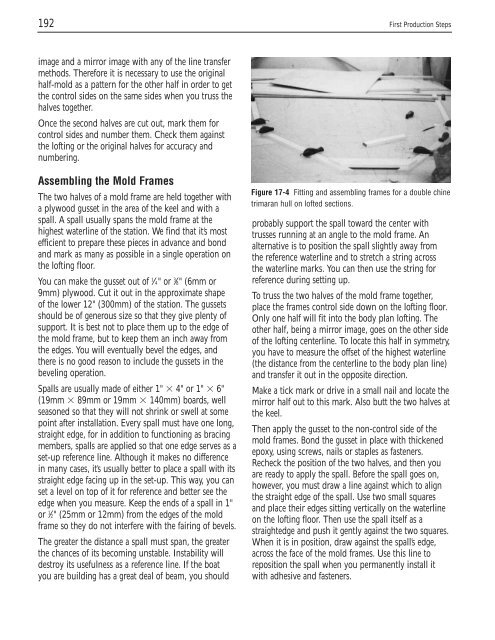
Figure 17-4 Fitting and assembling frames for a double chine<br />
trimaran hull <strong>on</strong> lofted secti<strong>on</strong>s.<br />
probably support the spall toward the center with<br />
trusses running at an angle to the mold frame. An<br />
alternative is to positi<strong>on</strong> the spall slightly away from<br />
the reference waterline and to stretch a string across<br />
the waterline marks. You can then use the string for<br />
reference during setting up.<br />
To truss the two halves of the mold frame together,<br />
place the frames c<strong>on</strong>trol side down <strong>on</strong> the lofting floor.<br />
Only <strong>on</strong>e half will fit into the body plan lofting. <str<strong>on</strong>g>The</str<strong>on</strong>g><br />
other half, being a mirror image, goes <strong>on</strong> the other side<br />
of the lofting centerline. To locate this half in symmetry,<br />
you have to measure the offset of the highest waterline<br />
(the distance from the centerline to the body plan line)<br />
and transfer it out in the opposite directi<strong>on</strong>.<br />
Make a tick mark or drive in a small nail and locate the<br />
mirror half out to this mark. Also butt the two halves at<br />
the keel.<br />
<str<strong>on</strong>g>The</str<strong>on</strong>g>n apply the gusset to the n<strong>on</strong>-c<strong>on</strong>trol side of the<br />
mold frames. B<strong>on</strong>d the gusset in place with thickened<br />
epoxy, using screws, nails or staples as fasteners.<br />
Recheck the positi<strong>on</strong> of the two halves, and then you<br />
are ready to apply the spall. Before the spall goes <strong>on</strong>,<br />
however, you must draw a line against which to align<br />
the straight edge of the spall. Use two small squares<br />
and place their edges sitting vertically <strong>on</strong> the waterline<br />
<strong>on</strong> the lofting floor. <str<strong>on</strong>g>The</str<strong>on</strong>g>n use the spall itself as a<br />
straightedge and push it gently against the two squares.<br />
When it is in positi<strong>on</strong>, draw against the spall’s edge,<br />
across the face of the mold frames. Use this line to<br />
repositi<strong>on</strong> the spall when you permanently install it<br />
with adhesive and fasteners.


