

The Gougeon Brothers on Boat Construction - WEST SYSTEM Epoxy
The Gougeon Brothers on Boat Construction - WEST SYSTEM Epoxy
The Gougeon Brothers on Boat Construction - WEST SYSTEM Epoxy

You also want an ePaper? Increase the reach of your titles
YUMPU automatically turns print PDFs into web optimized ePapers that Google loves.
Chapter 16 – Lofting 175<br />
crowded for the centerline and use a different ink<br />
color. <str<strong>on</strong>g>The</str<strong>on</strong>g>n take the marked stick over to the body<br />
plan grid and transfer all of the informati<strong>on</strong> to the<br />
appropriate waterlines, diag<strong>on</strong>als, and buttocks.<br />
Remember that the deck and profile have already been<br />
faired and w<strong>on</strong>’t appear <strong>on</strong> the measuring stick.<br />
When you have laid out all the points, bend a thin<br />
batten around them, trying to make it touch them all.<br />
Hold it in place with small nails—<strong>on</strong> either side of the<br />
batten, not hammered through it—or weights. If you<br />
find gross errors, go through the checking process<br />
explained earlier. Adjust the batten, moving it as little<br />
as possible from the points, until you have a fair, even<br />
curve, and then draw in the line in pencil.<br />
Lay out the rest of the stati<strong>on</strong> secti<strong>on</strong>s in this manner.<br />
We suggest laying down the points for <strong>on</strong>ly <strong>on</strong>e stati<strong>on</strong><br />
secti<strong>on</strong> and rough fairing that stati<strong>on</strong> secti<strong>on</strong> before you<br />
go <strong>on</strong> to another. Some stati<strong>on</strong> secti<strong>on</strong> lines will cross<br />
each other and if points exist for several secti<strong>on</strong>s, this<br />
can get somewhat c<strong>on</strong>fusing.<br />
It will help a little bit when it comes to final fairing<br />
if you use some c<strong>on</strong>sistency while rough fairing the<br />
secti<strong>on</strong> lines of the body plan. For example, if you<br />
move stati<strong>on</strong> 3 out slightly <strong>on</strong> the load waterline and<br />
stati<strong>on</strong> 2 needs correcti<strong>on</strong> in that area, make the correcti<strong>on</strong><br />
<strong>on</strong> stati<strong>on</strong> 2 by moving it out slightly at the load<br />
waterline rather than moving it in <strong>on</strong> waterline 1. By<br />
the time the body plan is laid down, although the boat<br />
is by no means fair yet, it is quite easy to envisi<strong>on</strong> the<br />
shape. Unless a major error is found, the secti<strong>on</strong> of the<br />
aftermost stati<strong>on</strong> in the body plan usually remains. On<br />
the forward half of the body plan, there is sometimes<br />
a line close to the centerline, but not necessarily parallel<br />
to it, which represents the thickness of the boat at<br />
the point where the planking ends, but before any<br />
rounding of the stem has taken place. You need to draw<br />
this line in also. It will later be used to determine the<br />
distance from center of the waterlines at the point<br />
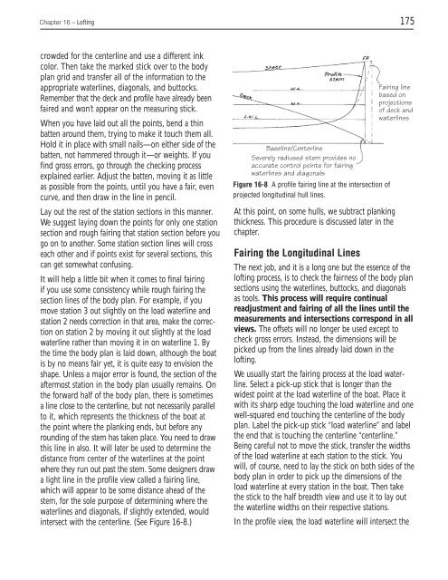
where they run out past the stem. Some designers draw<br />
a light line in the profile view called a fairing line,<br />
which will appear to be some distance ahead of the<br />
stem, for the sole purpose of determining where the<br />
waterlines and diag<strong>on</strong>als, if slightly extended, would<br />
intersect with the centerline. (See Figure 16-8.)<br />
Baseline/Centerline<br />
Severely radiused stem provides no<br />
accurate c<strong>on</strong>trol points for fairing<br />
waterlines and diag<strong>on</strong>als<br />
Figure 16-8 A profile fairing line at the intersecti<strong>on</strong> of<br />
projected l<strong>on</strong>gitudinal hull lines.<br />
At this point, <strong>on</strong> some hulls, we subtract planking<br />
thickness. This procedure is discussed later in the<br />
chapter.<br />
Fairing line<br />
based <strong>on</strong><br />
projecti<strong>on</strong>s<br />
of deck and<br />
waterlines<br />
Fairing the L<strong>on</strong>gitudinal Lines<br />
<str<strong>on</strong>g>The</str<strong>on</strong>g> next job, and it is a l<strong>on</strong>g <strong>on</strong>e but the essence of the<br />
lofting process, is to check the fairness of the body plan<br />
secti<strong>on</strong>s using the waterlines, buttocks, and diag<strong>on</strong>als<br />
as tools. This process will require c<strong>on</strong>tinual<br />
readjustment and fairing of all the lines until the<br />
measurements and intersecti<strong>on</strong>s corresp<strong>on</strong>d in all<br />
views. <str<strong>on</strong>g>The</str<strong>on</strong>g> offsets will no l<strong>on</strong>ger be used except to<br />
check gross errors. Instead, the dimensi<strong>on</strong>s will be<br />
picked up from the lines already laid down in the<br />
lofting.<br />
We usually start the fairing process at the load waterline.<br />
Select a pick-up stick that is l<strong>on</strong>ger than the<br />
widest point at the load waterline of the boat. Place it<br />
with its sharp edge touching the load waterline and <strong>on</strong>e<br />
well-squared end touching the centerline of the body<br />
plan. Label the pick-up stick “load waterline” and label<br />
the end that is touching the centerline “centerline.”<br />
Being careful not to move the stick, transfer the widths<br />
of the load waterline at each stati<strong>on</strong> to the stick. You<br />
will, of course, need to lay the stick <strong>on</strong> both sides of the<br />
body plan in order to pick up the dimensi<strong>on</strong>s of the<br />
load waterline at every stati<strong>on</strong> in the boat. <str<strong>on</strong>g>The</str<strong>on</strong>g>n take<br />
the stick to the half breadth view and use it to lay out<br />
the waterline widths <strong>on</strong> their respective stati<strong>on</strong>s.<br />
In the profile view, the load waterline will intersect the


