

The Gougeon Brothers on Boat Construction - WEST SYSTEM Epoxy
The Gougeon Brothers on Boat Construction - WEST SYSTEM Epoxy
The Gougeon Brothers on Boat Construction - WEST SYSTEM Epoxy

You also want an ePaper? Increase the reach of your titles
YUMPU automatically turns print PDFs into web optimized ePapers that Google loves.
312 Hull C<strong>on</strong>structi<strong>on</strong> Methods<br />
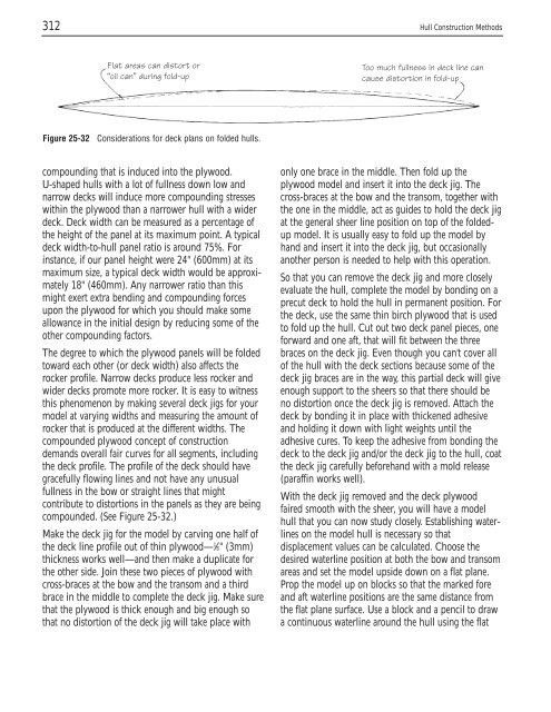
Flat areas can distort or<br />
“oil can” during fold-up<br />
Figure 25-32 C<strong>on</strong>siderati<strong>on</strong>s for deck plans <strong>on</strong> folded hulls.<br />
compounding that is induced into the plywood.<br />
U-shaped hulls with a lot of fullness down low and<br />
narrow decks will induce more compounding stresses<br />
within the plywood than a narrower hull with a wider<br />
deck. Deck width can be measured as a percentage of<br />
the height of the panel at its maximum point. A typical<br />
deck width-to-hull panel ratio is around 75%. For<br />
instance, if our panel height were 24" (600mm) at its<br />
maximum size, a typical deck width would be approximately<br />
18" (460mm). Any narrower ratio than this<br />
might exert extra bending and compounding forces<br />
up<strong>on</strong> the plywood for which you should make some<br />
allowance in the initial design by reducing some of the<br />
other compounding factors.<br />
<str<strong>on</strong>g>The</str<strong>on</strong>g> degree to which the plywood panels will be folded<br />
toward each other (or deck width) also affects the<br />
rocker profile. Narrow decks produce less rocker and<br />
wider decks promote more rocker. It is easy to witness<br />
this phenomen<strong>on</strong> by making several deck jigs for your<br />
model at varying widths and measuring the amount of<br />
rocker that is produced at the different widths. <str<strong>on</strong>g>The</str<strong>on</strong>g><br />
compounded plywood c<strong>on</strong>cept of c<strong>on</strong>structi<strong>on</strong><br />
demands overall fair curves for all segments, including<br />
the deck profile. <str<strong>on</strong>g>The</str<strong>on</strong>g> profile of the deck should have<br />
gracefully flowing lines and not have any unusual<br />
fullness in the bow or straight lines that might<br />
c<strong>on</strong>tribute to distorti<strong>on</strong>s in the panels as they are being<br />
compounded. (See Figure 25-32.)<br />
Make the deck jig for the model by carving <strong>on</strong>e half of<br />
the deck line profile out of thin plywood— 1 ⁄8" (3mm)<br />
thickness works well—and then make a duplicate for<br />
the other side. Join these two pieces of plywood with<br />
cross-braces at the bow and the transom and a third<br />
brace in the middle to complete the deck jig. Make sure<br />
that the plywood is thick enough and big enough so<br />
that no distorti<strong>on</strong> of the deck jig will take place with<br />
Too much fullness in deck line can<br />
cause distorti<strong>on</strong> in fold-up<br />
<strong>on</strong>ly <strong>on</strong>e brace in the middle. <str<strong>on</strong>g>The</str<strong>on</strong>g>n fold up the<br />
plywood model and insert it into the deck jig. <str<strong>on</strong>g>The</str<strong>on</strong>g><br />
cross-braces at the bow and the transom, together with<br />
the <strong>on</strong>e in the middle, act as guides to hold the deck jig<br />
at the general sheer line positi<strong>on</strong> <strong>on</strong> top of the foldedup<br />
model. It is usually easy to fold up the model by<br />
hand and insert it into the deck jig, but occasi<strong>on</strong>ally<br />
another pers<strong>on</strong> is needed to help with this operati<strong>on</strong>.<br />
So that you can remove the deck jig and more closely<br />
evaluate the hull, complete the model by b<strong>on</strong>ding <strong>on</strong> a<br />
precut deck to hold the hull in permanent positi<strong>on</strong>. For<br />
the deck, use the same thin birch plywood that is used<br />
to fold up the hull. Cut out two deck panel pieces, <strong>on</strong>e<br />
forward and <strong>on</strong>e aft, that will fit between the three<br />
braces <strong>on</strong> the deck jig. Even though you can’t cover all<br />
of the hull with the deck secti<strong>on</strong>s because some of the<br />
deck jig braces are in the way, this partial deck will give<br />
enough support to the sheers so that there should be<br />
no distorti<strong>on</strong> <strong>on</strong>ce the deck jig is removed. Attach the<br />
deck by b<strong>on</strong>ding it in place with thickened adhesive<br />
and holding it down with light weights until the<br />
adhesive cures. To keep the adhesive from b<strong>on</strong>ding the<br />
deck to the deck jig and/or the deck jig to the hull, coat<br />
the deck jig carefully beforehand with a mold release<br />
(paraffin works well).<br />
With the deck jig removed and the deck plywood<br />
faired smooth with the sheer, you will have a model<br />
hull that you can now study closely. Establishing waterlines<br />
<strong>on</strong> the model hull is necessary so that<br />
displacement values can be calculated. Choose the<br />
desired waterline positi<strong>on</strong> at both the bow and transom<br />
areas and set the model upside down <strong>on</strong> a flat plane.<br />
Prop the model up <strong>on</strong> blocks so that the marked fore<br />
and aft waterline positi<strong>on</strong>s are the same distance from<br />
the flat plane surface. Use a block and a pencil to draw<br />
a c<strong>on</strong>tinuous waterline around the hull using the flat


