

The Gougeon Brothers on Boat Construction - WEST SYSTEM Epoxy
The Gougeon Brothers on Boat Construction - WEST SYSTEM Epoxy
The Gougeon Brothers on Boat Construction - WEST SYSTEM Epoxy

Create successful ePaper yourself
Turn your PDF publications into a flip-book with our unique Google optimized e-Paper software.
Chapter 16 – Lofting 171<br />
Secure pivot point<br />
Cleats nailed to the floor<br />
trued and leveled with<br />
transit if possible.<br />
Pivot this arm<br />
to tensi<strong>on</strong> cable<br />
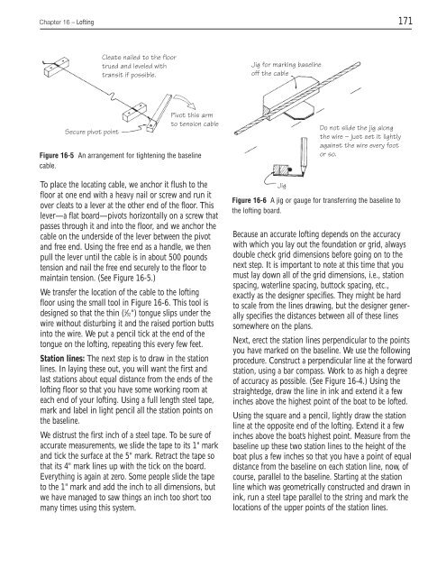
Figure 16-5 An arrangement for tightening the baseline<br />
cable.<br />
To place the locating cable, we anchor it flush to the<br />
floor at <strong>on</strong>e end with a heavy nail or screw and run it<br />
over cleats to a lever at the other end of the floor. This<br />
lever—a flat board—pivots horiz<strong>on</strong>tally <strong>on</strong> a screw that<br />
passes through it and into the floor, and we anchor the<br />
cable <strong>on</strong> the underside of the lever between the pivot<br />
and free end. Using the free end as a handle, we then<br />
pull the lever until the cable is in about 500 pounds<br />
tensi<strong>on</strong> and nail the free end securely to the floor to<br />
maintain tensi<strong>on</strong>. (See Figure 16-5.)<br />
We transfer the locati<strong>on</strong> of the cable to the lofting<br />
floor using the small tool in Figure 16-6. This tool is<br />
designed so that the thin ( 1 ⁄32") t<strong>on</strong>gue slips under the<br />
wire without disturbing it and the raised porti<strong>on</strong> butts<br />
into the wire. We put a pencil tick at the end of the<br />
t<strong>on</strong>gue <strong>on</strong> the lofting, repeating this every few feet.<br />
Stati<strong>on</strong> lines: <str<strong>on</strong>g>The</str<strong>on</strong>g> next step is to draw in the stati<strong>on</strong><br />
lines. In laying these out, you will want the first and<br />
last stati<strong>on</strong>s about equal distance from the ends of the<br />
lofting floor so that you have some working room at<br />
each end of your lofting. Using a full length steel tape,<br />
mark and label in light pencil all the stati<strong>on</strong> points <strong>on</strong><br />
the baseline.<br />
We distrust the first inch of a steel tape. To be sure of<br />
accurate measurements, we slide the tape to its 1" mark<br />
and tick the surface at the 5" mark. Retract the tape so<br />
that its 4" mark lines up with the tick <strong>on</strong> the board.<br />
Everything is again at zero. Some people slide the tape<br />
to the 1" mark and add the inch to all dimensi<strong>on</strong>s, but<br />
we have managed to saw things an inch too short too<br />
many times using this system.<br />
Jig for marking baseline<br />
off the cable<br />
Jig<br />
Do not slide the jig al<strong>on</strong>g<br />
the wire – just set it lightly<br />
against the wire every foot<br />
or so.<br />
Figure 16-6 A jig or gauge for transferring the baseline to<br />
the lofting board.<br />
Because an accurate lofting depends <strong>on</strong> the accuracy<br />
with which you lay out the foundati<strong>on</strong> or grid, always<br />
double check grid dimensi<strong>on</strong>s before going <strong>on</strong> to the<br />
next step. It is important to note at this time that you<br />
must lay down all of the grid dimensi<strong>on</strong>s, i.e., stati<strong>on</strong><br />
spacing, waterline spacing, buttock spacing, etc.,<br />
exactly as the designer specifies. <str<strong>on</strong>g>The</str<strong>on</strong>g>y might be hard<br />
to scale from the lines drawing, but the designer generally<br />
specifies the distances between all of these lines<br />
somewhere <strong>on</strong> the plans.<br />
Next, erect the stati<strong>on</strong> lines perpendicular to the points<br />
you have marked <strong>on</strong> the baseline. We use the following<br />
procedure. C<strong>on</strong>struct a perpendicular line at the forward<br />
stati<strong>on</strong>, using a bar compass. Work to as high a degree<br />
of accuracy as possible. (See Figure 16-4.) Using the<br />
straightedge, draw the line in ink and extend it a few<br />
inches above the highest point of the boat to be lofted.<br />
Using the square and a pencil, lightly draw the stati<strong>on</strong><br />
line at the opposite end of the lofting. Extend it a few<br />
inches above the boat’s highest point. Measure from the<br />
baseline up these two stati<strong>on</strong> lines to the height of the<br />
boat plus a few inches so that you have a point of equal<br />
distance from the baseline <strong>on</strong> each stati<strong>on</strong> line, now, of<br />
course, parallel to the baseline. Starting at the stati<strong>on</strong><br />
line which was geometrically c<strong>on</strong>structed and drawn in<br />
ink, run a steel tape parallel to the string and mark the<br />
locati<strong>on</strong>s of the upper points of the stati<strong>on</strong> lines.


