

The Gougeon Brothers on Boat Construction - WEST SYSTEM Epoxy
The Gougeon Brothers on Boat Construction - WEST SYSTEM Epoxy
The Gougeon Brothers on Boat Construction - WEST SYSTEM Epoxy

Create successful ePaper yourself
Turn your PDF publications into a flip-book with our unique Google optimized e-Paper software.
174 First Producti<strong>on</strong> Steps<br />
did the sheer line. Double check any major errors and<br />
then move the batten just enough so that it forms a fair,<br />
even curve. Draw in the deck line in ink. <str<strong>on</strong>g>The</str<strong>on</strong>g> lines that<br />
you have drawn so far are final, and it w<strong>on</strong>’t be necessary<br />
to change them during the lofting process.<br />
Body Plan Secti<strong>on</strong>s<br />
With the drawing of the grid, profile lines, and deck<br />
line, the primary lines of the lofting are complete. <str<strong>on</strong>g>The</str<strong>on</strong>g><br />
next step is to lay out the body plan, which is the secti<strong>on</strong><br />
view of the stati<strong>on</strong>s. <str<strong>on</strong>g>The</str<strong>on</strong>g> profile lines and the deck line,<br />
drawn in ink, will give you the height of the keel profile<br />
above the baseline and the height and width of the sheer<br />
at any given stati<strong>on</strong>. <str<strong>on</strong>g>The</str<strong>on</strong>g> first job is to transfer these<br />
dimensi<strong>on</strong>s—as faired, not as given in the table of<br />
offsets—from the profile and half breadth views to<br />
the body plan using pick-up sticks.<br />
Pick-up sticks do just that: they pick up a dimensi<strong>on</strong><br />
from <strong>on</strong>e area of the lofting and transfer it to another<br />
area or view. <str<strong>on</strong>g>The</str<strong>on</strong>g>y are much easier to use and provide<br />
less chance for error than a steel measuring tape.<br />
Pick any stati<strong>on</strong> to start with in transferring the profile<br />
and sheer points to the body plan. Lay the pick-up stick<br />
al<strong>on</strong>g the stati<strong>on</strong> line so that it is touching the block at<br />
the baseline and the fine edge of the pick-up stick just<br />
touches the stati<strong>on</strong> line. In using the pick-up sticks,<br />
always label what stati<strong>on</strong> line, waterline, or other informati<strong>on</strong><br />
you are transferring. In this case, you would<br />
write the stati<strong>on</strong> number and baseline <strong>on</strong> the end of the<br />
sticks touching the baseline. <str<strong>on</strong>g>The</str<strong>on</strong>g>n you would mark and<br />
label the keel profile height, the sheer height, and the<br />
deck width. <str<strong>on</strong>g>The</str<strong>on</strong>g>n take the pick-up stick to the body<br />
plan grid and lay it al<strong>on</strong>g the centerline, touching the<br />
baseline block in the profile view. Mark the height of<br />
the keel profile and sheer <strong>on</strong> the centerline. Lay out the<br />
stati<strong>on</strong>s <strong>on</strong> the body plan <strong>on</strong> the same side of the<br />
centerline as the designer has drawn them in the plans.<br />
To locate the half breadth deck point, draw a line out at<br />
right angles to the centerline at the height of the sheer.<br />
Most loftsmen use the adjacent stati<strong>on</strong> to lay out the<br />
sheer height and c<strong>on</strong>nect the two points with the<br />
straightedge, drawing in a light pencil line. <str<strong>on</strong>g>The</str<strong>on</strong>g>n,<br />
measure out from center <strong>on</strong> this line for the sheer point.<br />
This is slightly more accurate than using a square off<br />
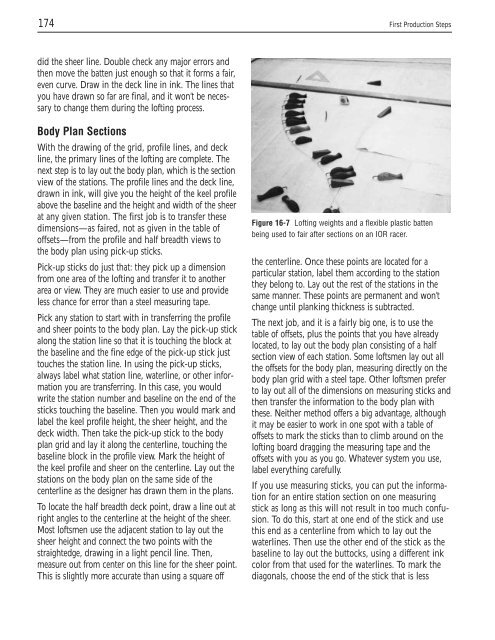
Figure 16-7 Lofting weights and a flexible plastic batten<br />
being used to fair after secti<strong>on</strong>s <strong>on</strong> an IOR racer.<br />
the centerline. Once these points are located for a<br />
particular stati<strong>on</strong>, label them according to the stati<strong>on</strong><br />
they bel<strong>on</strong>g to. Lay out the rest of the stati<strong>on</strong>s in the<br />
same manner. <str<strong>on</strong>g>The</str<strong>on</strong>g>se points are permanent and w<strong>on</strong>’t<br />
change until planking thickness is subtracted.<br />
<str<strong>on</strong>g>The</str<strong>on</strong>g> next job, and it is a fairly big <strong>on</strong>e, is to use the<br />
table of offsets, plus the points that you have already<br />
located, to lay out the body plan c<strong>on</strong>sisting of a half<br />
secti<strong>on</strong> view of each stati<strong>on</strong>. Some loftsmen lay out all<br />
the offsets for the body plan, measuring directly <strong>on</strong> the<br />
body plan grid with a steel tape. Other loftsmen prefer<br />
to lay out all of the dimensi<strong>on</strong>s <strong>on</strong> measuring sticks and<br />
then transfer the informati<strong>on</strong> to the body plan with<br />
these. Neither method offers a big advantage, although<br />
it may be easier to work in <strong>on</strong>e spot with a table of<br />
offsets to mark the sticks than to climb around <strong>on</strong> the<br />
lofting board dragging the measuring tape and the<br />
offsets with you as you go. Whatever system you use,<br />
label everything carefully.<br />
If you use measuring sticks, you can put the informati<strong>on</strong><br />
for an entire stati<strong>on</strong> secti<strong>on</strong> <strong>on</strong> <strong>on</strong>e measuring<br />
stick as l<strong>on</strong>g as this will not result in too much c<strong>on</strong>fusi<strong>on</strong>.<br />
To do this, start at <strong>on</strong>e end of the stick and use<br />
this end as a centerline from which to lay out the<br />
waterlines. <str<strong>on</strong>g>The</str<strong>on</strong>g>n use the other end of the stick as the<br />
baseline to lay out the buttocks, using a different ink<br />
color from that used for the waterlines. To mark the<br />
diag<strong>on</strong>als, choose the end of the stick that is less


