

The Gougeon Brothers on Boat Construction - WEST SYSTEM Epoxy
The Gougeon Brothers on Boat Construction - WEST SYSTEM Epoxy
The Gougeon Brothers on Boat Construction - WEST SYSTEM Epoxy

You also want an ePaper? Increase the reach of your titles
YUMPU automatically turns print PDFs into web optimized ePapers that Google loves.
178 First Producti<strong>on</strong> Steps<br />
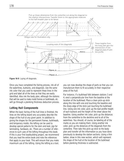
Figure 16-9 Laying off diag<strong>on</strong>als.<br />
Pick up these dimensi<strong>on</strong>s from the centerline out al<strong>on</strong>g the diag<strong>on</strong>al to<br />
the stati<strong>on</strong> intersecti<strong>on</strong>s. Transfer them to the appropriate stati<strong>on</strong>s<br />
in the half breadth plan to be faired.<br />
Oblique view for illustrati<strong>on</strong> <strong>on</strong>ly<br />
Locating ends of the diag<strong>on</strong>als<br />
Once you have completed the fairing process, ink all of<br />
the waterlines, buttocks, and diag<strong>on</strong>als. Use the same<br />
ink color that you used to represent these lines in the<br />
grid and label all of the lines so that they are easily<br />
identified. Also ink the body plan, although the stati<strong>on</strong>s<br />
that will be used to make mold frames or bulkheads, etc.<br />
will go through a planking thickness deducti<strong>on</strong> process.<br />
Lofting Hull Comp<strong>on</strong>ents<br />
When the basic fairing of the hull lines is finished, the<br />
lines <strong>on</strong> the lofting board very accurately describe the<br />
shape of the hull at any given point. In additi<strong>on</strong> to<br />
giving the shapes for the permanent frames, bulkheads,<br />
and temporary molds, the lofting can be used to<br />
develop special patterns for the stem and keel, jigs for<br />
laminating, hardware, etc. <str<strong>on</strong>g>The</str<strong>on</strong>g>re are a number of references<br />
to such uses of the lofting throughout this book.<br />
If this is your first boatbuilding project, we recommend<br />
that you read the entire book and note the references<br />
that apply to your boat. This will ensure that you make<br />
maximum use of the lofting. Using the lofting as a tool,<br />
<str<strong>on</strong>g>The</str<strong>on</strong>g>se heights from<br />
the body plan give the<br />
intersecti<strong>on</strong> of the<br />
diag<strong>on</strong>al plane B with<br />
the profile.<br />
you can now develop the shape of parts so that you can<br />
manufacture them to fit accurately in their respective<br />
areas of the hull.<br />
For instance, if a bulkhead falls between stati<strong>on</strong>s 3 and<br />
4, erect a perpendicular line from the baseline at the<br />
locati<strong>on</strong> of the bulkhead. Place a clean pick-up stick<br />
al<strong>on</strong>g this line with <strong>on</strong>e end touching the baseline and<br />
the sharp edge of the stick just touching the bulkhead<br />
line. Using <strong>on</strong>e ink color, pick up the keel profile height<br />
of each buttock and the height of the sheer above the<br />
baseline. Using another ink color, pick up the distances<br />
from the centerline to the deckline and to all of the<br />
waterlines. You should, of course, be labeling all of the<br />
marks as you are making them. Using another ink<br />
color, pick up the distances of the diag<strong>on</strong>als from the<br />
centerline. <str<strong>on</strong>g>The</str<strong>on</strong>g>n take this pick-up stick to the body<br />
plan and transfer all the informati<strong>on</strong> as you have d<strong>on</strong>e<br />
previously to develop the stati<strong>on</strong> secti<strong>on</strong>s. Using a thin<br />
batten, draw in this new secti<strong>on</strong>, which will represent<br />
the shape of the hull at the locati<strong>on</strong> of the bulkhead<br />
before planking thickness is subtracted.


