

The Gougeon Brothers on Boat Construction - WEST SYSTEM Epoxy
The Gougeon Brothers on Boat Construction - WEST SYSTEM Epoxy
The Gougeon Brothers on Boat Construction - WEST SYSTEM Epoxy

You also want an ePaper? Increase the reach of your titles
YUMPU automatically turns print PDFs into web optimized ePapers that Google loves.
132 Core <strong>Boat</strong>building Techniques<br />
may be higher than the value derived above, but we<br />
recommend using the c<strong>on</strong>servative value for estimati<strong>on</strong>.<br />
For most applicati<strong>on</strong>s where the shear strength of the<br />
wood is greater than 800 psi, we recommend a hole<br />
sized 1 ⁄4" (6mm) larger in diameter than the major<br />
diameter of the bolt. This gives an epoxy annulus of<br />
1 ⁄8" (3mm) around the bolt. We vary the length of the<br />
bolt and depth of the hole to balance the breaking<br />
strength of the bolt versus the withdrawal resistance<br />
of the epoxy plug. <str<strong>on</strong>g>The</str<strong>on</strong>g> 800 psi epoxy shear strength<br />
is the limiting value.<br />
<str<strong>on</strong>g>The</str<strong>on</strong>g> following example shows how to determine the<br />
diameter and depth of an oversize hole so that the force<br />
required to extract the fastener is approximately equal<br />
to the breaking strength of the bolt:<br />
A 3 ⁄8" diameter 18-8 stainless-steel bolt with an ultimate<br />
tensile strength of 85,000 psi and an effective crosssecti<strong>on</strong>al<br />
working area of 0.0775 square inches has<br />
a breaking strength of 6,587 pounds. <str<strong>on</strong>g>The</str<strong>on</strong>g> hole depth<br />
should be the breaking strength (6,600 pounds)<br />
divided by the epoxy shear strength (800 psi), divided<br />
by the circumference of the hole (0.625" � 3.1416 =<br />
1.9635") to equal 4.20". In actual practice, we used<br />
a 5 ⁄8" diameter hole with a depth of 41 ⁄2" for a 3 ⁄8"<br />
diameter bolt with 41 ⁄4" inches of b<strong>on</strong>ded length.<br />
<str<strong>on</strong>g>The</str<strong>on</strong>g> above calculati<strong>on</strong>s need to be modified when you<br />
are limited in the depth of the hole allowed or when<br />
a short or oversized bolt is specified in the hardware<br />
installati<strong>on</strong>. You do not want to cut away large porti<strong>on</strong>s<br />
of a keel or floor by using a grossly oversized hole.<br />
Likewise, you may be limited in a deck applicati<strong>on</strong> by<br />
blocking locati<strong>on</strong> or overhead space limitati<strong>on</strong>s. In such<br />
cases, it is best to use the 1 ⁄4" larger diameter, epoxyfilled<br />
hole to assist in stabilizing and securing the keel<br />
bolt, but use floors or metal pads to distribute the load.<br />
How the surface area of the hole affects small and large<br />
fasteners is discussed below.<br />
Small fasteners in tensi<strong>on</strong><br />
In 1978 and 1979, we c<strong>on</strong>ducted tests to determine<br />
the relative effects of surface area <strong>on</strong> fasteners. We<br />
compared tensi<strong>on</strong> withdrawal of 11 ⁄2" l<strong>on</strong>g flathead<br />
wood screws, ranging in size from No. 8 through No.<br />
14, in dry pilot holes and oversize holes from 3 ⁄16" to 3 ⁄4"<br />
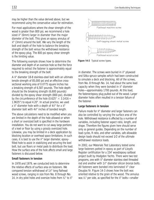
Flathead machine screw<br />
Figure 14-2 Typical screw types.<br />
Self-tapping sheet metal screw<br />
Flathead wood screw<br />
in diameter. <str<strong>on</strong>g>The</str<strong>on</strong>g> screws were buried in 1 ⁄4" plywood<br />
and Sitka spruce samples which had been c<strong>on</strong>structed<br />
to simulate a deck and blocking. All of the screws,<br />
from No. 8 through No. 14, had about the same load<br />
capacity when they were b<strong>on</strong>ded in 1 ⁄4" diameter<br />
holes—approximately 1700 pounds. At this load,<br />
the fastener/epoxy plug pulled out of the wood. Larger<br />
diameter holes often resulted in a tensi<strong>on</strong> failure of<br />
the fastener.<br />
Large fasteners in tensi<strong>on</strong><br />
Failure mode for 3 ⁄4" diameter and larger fasteners can<br />
also be c<strong>on</strong>trolled by varying the surface area of the<br />
hole. Withdrawal resistance is affected by a number of<br />
variables, including fastener aspect ratio, length, and<br />
shape. <str<strong>on</strong>g>The</str<strong>on</strong>g>refore the figures given here should serve<br />
<strong>on</strong>ly as general guides. Depending <strong>on</strong> the number of<br />
load cycles, R ratio, and other variables, safe allowable<br />
design loads should not exceed 1⁄2 of the ultimate<br />
withdrawal resistance loads.<br />
In 2002, our Materials Test Laboratory tested some<br />
large fasteners potted in epoxy as part of Lloyd’s<br />
Register certificati<strong>on</strong> for a 154' wood/epoxy sailboat<br />
project built by Hodgd<strong>on</strong> Yachts. <str<strong>on</strong>g>The</str<strong>on</strong>g>re were two test<br />
programs, <strong>on</strong>e with 3 ⁄4" diameter stainless steel threaded<br />
rod and another with 11 ⁄2" diameter silic<strong>on</strong> br<strong>on</strong>ze bolts.<br />
All fasteners were b<strong>on</strong>ded into laminated 3 ⁄4" clear<br />
Douglas fir. Figure 14-3 shows how the bolt was<br />
oriented relative to the grain of the wood. <str<strong>on</strong>g>The</str<strong>on</strong>g> annulus<br />
was 1 ⁄16" per side, as specified for the 3 ⁄4" bolts—smaller


