

The Gougeon Brothers on Boat Construction - WEST SYSTEM Epoxy
The Gougeon Brothers on Boat Construction - WEST SYSTEM Epoxy
The Gougeon Brothers on Boat Construction - WEST SYSTEM Epoxy

You also want an ePaper? Increase the reach of your titles
YUMPU automatically turns print PDFs into web optimized ePapers that Google loves.
180 First Producti<strong>on</strong> Steps<br />
case you may have to move the batten slightly in order<br />
to make the secti<strong>on</strong> fair. If there is a major error, go<br />
back and check through the development process. When<br />
everything is right, this transom or angled bulkhead will<br />
look similar to the vertical stati<strong>on</strong>s <strong>on</strong> either side,<br />
although it will be expanded or more drawn out.<br />
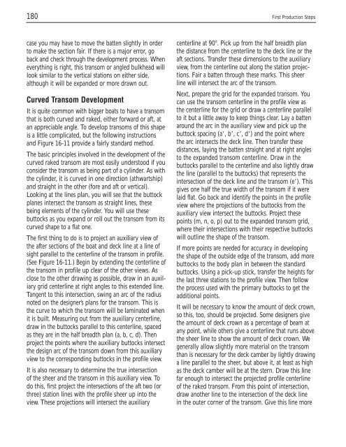
Curved Transom Development<br />
It is quite comm<strong>on</strong> with bigger boats to have a transom<br />
that is both curved and raked, either forward or aft, at<br />
an appreciable angle. To develop transoms of this shape<br />
is a little complicated, but the following instructi<strong>on</strong>s<br />
and Figure 16-11 provide a fairly standard method.<br />
<str<strong>on</strong>g>The</str<strong>on</strong>g> basic principles involved in the development of the<br />
curved raked transom are most easily understood if you<br />
c<strong>on</strong>sider the transom as being part of a cylinder. As with<br />
the cylinder, it is curved in <strong>on</strong>e directi<strong>on</strong> (athwartship)<br />
and straight in the other (fore and aft or vertical).<br />
Looking at the lines plan, you will see that the buttock<br />
planes intersect the transom as straight lines, these<br />
being elements of the cylinder. You will use these<br />
buttocks as you expand or roll out the transom from its<br />
curved shape to a flat <strong>on</strong>e.<br />
<str<strong>on</strong>g>The</str<strong>on</strong>g> first thing to do is to project an auxiliary view of<br />
the after secti<strong>on</strong>s of the boat and deck line at a line of<br />
sight parallel to the centerline of the transom in profile.<br />
(See Figure 16-11.) Begin by extending the centerline of<br />
the transom in profile up clear of the other views. As<br />
close to the other drawing as possible, draw in an auxiliary<br />
grid centerline at right angles to this extended line.<br />
Tangent to this intersecti<strong>on</strong>, swing an arc of the radius<br />
noted <strong>on</strong> the designer’s plans for the transom. This is<br />
the curve to which the transom will be laminated when<br />
it is built. Measuring out from the auxiliary centerline,<br />
draw in the buttocks parallel to this centerline, spaced<br />
as they are in the half breadth plan (a, b, c, d). <str<strong>on</strong>g>The</str<strong>on</strong>g>n<br />
project the points where the auxiliary buttocks intersect<br />
the design arc of the transom down from this auxiliary<br />
view to the corresp<strong>on</strong>ding buttocks in the profile view.<br />
It is also necessary to determine the true intersecti<strong>on</strong><br />
of the sheer and the transom in this auxiliary view. To<br />
do this, first project the intersecti<strong>on</strong>s of the aft two (or<br />
three) stati<strong>on</strong> lines with the profile sheer up into the<br />
view. <str<strong>on</strong>g>The</str<strong>on</strong>g>se projecti<strong>on</strong>s will intersect the auxiliary<br />
centerline at 90°. Pick up from the half breadth plan<br />
the distance from the centerline to the deck line or the<br />
aft secti<strong>on</strong>s. Transfer these dimensi<strong>on</strong>s to the auxiliary<br />
view, from the centerline out al<strong>on</strong>g the stati<strong>on</strong> projecti<strong>on</strong>s.<br />
Fair a batten through these marks. This sheer<br />
line will intersect the arc of the transom.<br />
Next, prepare the grid for the expanded transom. You<br />
can use the transom centerline in the profile view as<br />
the centerline for the grid or draw a centerline parallel<br />
to it but a little away to keep things clear. Lay a batten<br />
around the arc in the auxiliary view and pick up the<br />
buttock spacing (a�, b�, c�, d�) and the point where<br />
the arc intersects the deck line. <str<strong>on</strong>g>The</str<strong>on</strong>g>n transfer these<br />
distances, laying the batten straight and at right angles<br />
to the expanded transom centerline. Draw in the<br />
buttocks parallel to the centerline and also lightly draw<br />
the line (parallel to the buttocks) that represents the<br />
intersecti<strong>on</strong> of the deck line and the transom (e�). This<br />
gives <strong>on</strong>e half the true width of the transom if it were<br />
laid flat. Go back and identify the points in the profile<br />
view where the projecti<strong>on</strong>s of the buttocks from the<br />
auxiliary view intersect the buttocks. Project these<br />
points (m, n, o, p) out to the expanded transom grid,<br />
where their intersecti<strong>on</strong>s with their respective buttocks<br />
will outline the shape of the transom.<br />
If more points are needed for accuracy in developing<br />
the shape of the outside edge of the transom, add more<br />
buttocks to the body plan in between the standard<br />
buttocks. Using a pick-up stick, transfer the heights for<br />
the last three stati<strong>on</strong>s to the profile view. <str<strong>on</strong>g>The</str<strong>on</strong>g>n follow<br />
the process used with the primary buttocks to get the<br />
additi<strong>on</strong>al points.<br />
It will be necessary to know the amount of deck crown,<br />
so this, too, should be projected. Some designers give<br />
the amount of deck crown as a percentage of beam at<br />
any point, while others give a centerline that runs above<br />
the sheer line to show the amount of deck crown. We<br />
generally allow slightly more material <strong>on</strong> the transom<br />
than is necessary for the deck camber by lightly drawing<br />
a line parallel to the sheer, but above it, at least as high<br />
as the deck camber will be at the stern. Draw this line<br />
far enough to intersect the projected profile centerline<br />
of the raked transom. From this point of intersecti<strong>on</strong>,<br />
draw another line to the intersecti<strong>on</strong> of the deck line<br />
in the outer corner of the transom. Give this line more


