

The Gougeon Brothers on Boat Construction - WEST SYSTEM Epoxy
The Gougeon Brothers on Boat Construction - WEST SYSTEM Epoxy
The Gougeon Brothers on Boat Construction - WEST SYSTEM Epoxy

You also want an ePaper? Increase the reach of your titles
YUMPU automatically turns print PDFs into web optimized ePapers that Google loves.
206 First Producti<strong>on</strong> Steps<br />
Beveling<br />
Frames are beveled so that planking can bend evenly,<br />
with smooth curves, over them. Begin this operati<strong>on</strong> by<br />
rolling flat black paint <strong>on</strong> the edges of the frames. Most<br />
of this paint will be planed away; the object is to leave<br />
a thin line of black <strong>on</strong> the c<strong>on</strong>trolling edge so that you<br />
know it has not been disturbed.<br />
Use a batten that spans at least three stati<strong>on</strong>s as a guide<br />
for beveling. Lay it over three frames and nail down its<br />
ends. If your mold frames are <strong>on</strong>ly 1 ⁄4" (6mm) thick,<br />
you can just hack away excess stock from the middle<br />
frame. If they are thicker, take a handsaw and cut<br />
marks <strong>on</strong> the edge of the middle frame <strong>on</strong> either side of<br />
the batten parallel to it as it crosses the frame edge at an<br />
angle. Cut no deeper than the black c<strong>on</strong>trol edge. Move<br />
the batten up and down the frame, sawing or hacking<br />
every foot al<strong>on</strong>g its edge. Check for fairness. When you<br />
have finished <strong>on</strong>e frame, move <strong>on</strong> to the next.<br />
When all larger frames are marked, chisel away the<br />
wood between the kerfs so that you have a series of<br />
notches. Check again for fairness, and then scribble<br />
across the bottom of each notch with a pencil. Using<br />
the pencil marks to guide you, plane the entire edge of<br />
the frame. We use power planes to rough-cut bevels,<br />
but advise against them unless you have some experience<br />
with these machines. Hand planes do just as well,<br />
though at a somewhat slower rate.<br />
Fairing<br />
Once you have rough cut the bevels so that <strong>on</strong>ly a thin<br />
line of black remains <strong>on</strong> the c<strong>on</strong>trolling edges, you are<br />
ready for final fairing. As in lofting, the eye and artistic<br />
sensitivity are the main tools. <str<strong>on</strong>g>The</str<strong>on</strong>g> object is to make the<br />
l<strong>on</strong>g batten touch all the c<strong>on</strong>trolling edges under it and<br />
form a curve free of lumps or flat spots in all positi<strong>on</strong>s<br />
<strong>on</strong> the length of the set-up.<br />
To accomplish this, it may be necessary to cut below<br />
the marked black c<strong>on</strong>trol edge in some areas, and to<br />
build up above the edge in others by b<strong>on</strong>ding <strong>on</strong> strips<br />
of wood or not beveling to the full depth of the saw<br />
cuts. Accurate work in lofting, picking up, cutting<br />
frames, c<strong>on</strong>structing them, and setting them up will<br />
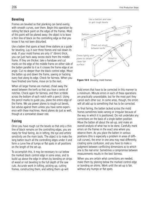
Use a batten and saw<br />
to get rough bevels<br />
Batten Molds<br />
Dress lightly with<br />
plane to obtain<br />
clean fair<br />
surface<br />
Chisel out stock<br />
between kerfs<br />
Chisel to<br />
marks<br />
Figure 18-9 Beveling mold frames.<br />
hold errors that have to be corrected in this manner to<br />
a minimum. Minute errors in each of these operati<strong>on</strong>s<br />
are practically unavoidable, but for the most part they<br />
cancel each other out. In some areas, though, the errors<br />
will all add up to something that has to be corrected.<br />
In final fairing, the batten tacked across the mold<br />
frames sometimes looks wr<strong>on</strong>g or irregular because of<br />
the way in which it is positi<strong>on</strong>ed. Do not undertake any<br />
correcti<strong>on</strong>s <strong>on</strong> the basis of a single batten positi<strong>on</strong>.<br />
Move the batten all about the set-up, and make an<br />
overall analysis of what has to be d<strong>on</strong>e. Carefully mark<br />
errors <strong>on</strong> the frames in the exact area where you<br />
observe them. As you place the batten in various<br />
positi<strong>on</strong>s (this is especially a problem in areas of difficult<br />
curves), the error in <strong>on</strong>e area may read differently,<br />
creating some c<strong>on</strong>fusi<strong>on</strong>, and you have to make a<br />
judgment between c<strong>on</strong>flicting dimensi<strong>on</strong>s as to which<br />
<strong>on</strong>e is the real error. Sometimes a compromise between<br />
measurements results in the best fairness.<br />
When you are certain what correcti<strong>on</strong>s are needed,<br />
make them by planing below the marked c<strong>on</strong>trol edge<br />
or b<strong>on</strong>ding <strong>on</strong> shims. Work until the set-up is fair,<br />
without any humps or flat spots.


