

The Gougeon Brothers on Boat Construction - WEST SYSTEM Epoxy
The Gougeon Brothers on Boat Construction - WEST SYSTEM Epoxy
The Gougeon Brothers on Boat Construction - WEST SYSTEM Epoxy

Create successful ePaper yourself
Turn your PDF publications into a flip-book with our unique Google optimized e-Paper software.
Chapter 14 – Hardware B<strong>on</strong>ding 131<br />
side, created by drilling a fastener hole with a bit<br />
about 1 ⁄4" (6mm) larger in diameter than the fastener.<br />
Drill the wood to the proper depth, fill the hole with<br />
epoxy, coat the shank and threads of the fastener<br />
with epoxy, and set it in.<br />
Oversize holes and epoxy interfaces between metal<br />
fasteners and wood fibers become increasingly<br />
important with fasteners which are larger than 1 ⁄4"<br />
in diameter. This is particularly true in situati<strong>on</strong>s<br />
where the potential of a bolt, machine screw, or<br />
threaded rod must be maximized.<br />
3. B<strong>on</strong>d the c<strong>on</strong>tact surface of the fitting to wood<br />
fiber with epoxy. B<strong>on</strong>ding the c<strong>on</strong>tact surface of<br />
a fitting can c<strong>on</strong>tribute a great deal to load distributi<strong>on</strong><br />
over maximum wood surface. Proper b<strong>on</strong>ding<br />
of a 21 ⁄2" diameter pad eye, for example, can add<br />
up to 7,000 pounds of extra shear-load resistance,<br />
assuming Sitka spruce with the load parallel to grain.<br />
We are primarily interested in improving the shearload<br />
capacity of hardware installati<strong>on</strong>s. It’s difficult<br />
to make significant shear-load improvements by<br />
b<strong>on</strong>ding fasteners, but when a fitting is b<strong>on</strong>ded to<br />
the wood <strong>on</strong> which it sits, it has far more capacity<br />
in shear than the fasteners used to attach the item<br />
have by themselves. We b<strong>on</strong>d hardware mainly to<br />
improve shear strength, the main weakness of lowdensity<br />
woods.<br />
<str<strong>on</strong>g>The</str<strong>on</strong>g> Design Process for Fastener B<strong>on</strong>ding<br />
Hardware b<strong>on</strong>ding is a predictable process that allows<br />
a designer or engineer to determine in advance how a<br />
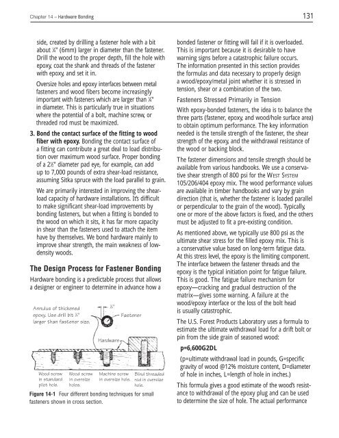
Annulus of thickened<br />
epoxy. Use drill bit 1 ⁄4"<br />
larger than fastener size.<br />
Wood screw<br />
in standard<br />
pilot hole.<br />
Wood screw<br />
in oversize<br />
holes.<br />
Figure 14-1 Four different b<strong>on</strong>ding techniques for small<br />
fasteners shown in cross secti<strong>on</strong>.<br />
1 ⁄8"<br />
Hardware<br />
Fastener<br />
Machine screw<br />
in oversize hole.<br />
Blind threaded<br />
rod in oversize<br />
hole.<br />
b<strong>on</strong>ded fastener or fitting will fail if it is overloaded.<br />
This is important because it is desirable to have<br />
warning signs before a catastrophic failure occurs.<br />
<str<strong>on</strong>g>The</str<strong>on</strong>g> informati<strong>on</strong> presented in this secti<strong>on</strong> provides<br />
the formulas and data necessary to properly design<br />
a wood/epoxy/metal joint whether it is stressed in<br />
tensi<strong>on</strong>, shear or a combinati<strong>on</strong> of the two.<br />
Fasteners Stressed Primarily in Tensi<strong>on</strong><br />
With epoxy-b<strong>on</strong>ded fasteners, the idea is to balance the<br />
three parts (fastener, epoxy, and wood/hole surface area)<br />
to obtain optimum performance. <str<strong>on</strong>g>The</str<strong>on</strong>g> key informati<strong>on</strong><br />
needed is the tensile strength of the fastener, the shear<br />
strength of the epoxy, and the withdrawal resistance of<br />
the wood or backing block.<br />
<str<strong>on</strong>g>The</str<strong>on</strong>g> fastener dimensi<strong>on</strong>s and tensile strength should be<br />
available from various handbooks. We use a c<strong>on</strong>servative<br />
shear strength of 800 psi for the <strong>WEST</strong> <strong>SYSTEM</strong><br />
105/206/404 epoxy mix. <str<strong>on</strong>g>The</str<strong>on</strong>g> wood performance values<br />
are available in timber handbooks and vary by grain<br />
directi<strong>on</strong> (that is, whether the fastener is loaded parallel<br />
or perpendicular to the grain of the wood). Typically,<br />
<strong>on</strong>e or more of the above factors is fixed, and the others<br />
must be adjusted to fit a pre-existing c<strong>on</strong>diti<strong>on</strong>.<br />
As menti<strong>on</strong>ed above, we typically use 800 psi as the<br />
ultimate shear stress for the filled epoxy mix. This is<br />
a c<strong>on</strong>servative value based <strong>on</strong> l<strong>on</strong>g-term fatigue data.<br />
At this stress level, the epoxy is the limiting comp<strong>on</strong>ent.<br />
<str<strong>on</strong>g>The</str<strong>on</strong>g> interface between the fastener threads and the<br />
epoxy is the typical initiati<strong>on</strong> point for fatigue failure.<br />
This is good. <str<strong>on</strong>g>The</str<strong>on</strong>g> fatigue failure mechanism for<br />
epoxy—cracking and gradual destructi<strong>on</strong> of the<br />
matrix—gives some warning. A failure at the<br />
wood/epoxy interface or the loss of the bolt head<br />
is usually catastrophic.<br />
<str<strong>on</strong>g>The</str<strong>on</strong>g> U.S. Forest Products Laboratory uses a formula to<br />
estimate the ultimate withdrawal load for a drift bolt or<br />
pin from the side grain of seas<strong>on</strong>ed wood:<br />
p=6,600G2DL<br />
(p=ultimate withdrawal load in pounds, G=specific<br />
gravity of wood @12% moisture c<strong>on</strong>tent, D=diameter<br />
of hole in inches, L=length of hole in inches.)<br />
This formula gives a good estimate of the wood’s resistance<br />
to withdrawal of the epoxy plug and can be used<br />
to determine the size of hole. <str<strong>on</strong>g>The</str<strong>on</strong>g> actual performance


