

The Gougeon Brothers on Boat Construction - WEST SYSTEM Epoxy
The Gougeon Brothers on Boat Construction - WEST SYSTEM Epoxy
The Gougeon Brothers on Boat Construction - WEST SYSTEM Epoxy

Create successful ePaper yourself
Turn your PDF publications into a flip-book with our unique Google optimized e-Paper software.
166 First Producti<strong>on</strong> Steps<br />
Hull Lines Drawings<br />
<str<strong>on</strong>g>The</str<strong>on</strong>g> lines drawings will show three different views of<br />
the boat. Figure 16-2 shows a simple set of lines. <str<strong>on</strong>g>The</str<strong>on</strong>g><br />
profile is the shape of the boat from a side view. <str<strong>on</strong>g>The</str<strong>on</strong>g><br />
half breadth plan is the top view from the deck. <str<strong>on</strong>g>The</str<strong>on</strong>g><br />
body plan is the end view of the boat from either bow<br />
or stern.<br />
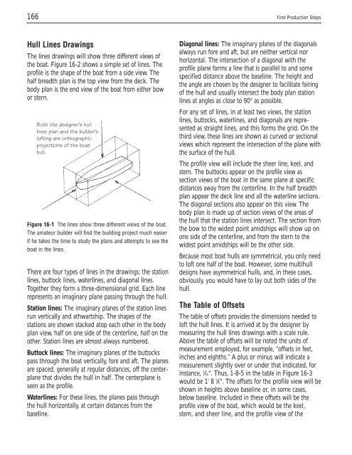
Both the designer’s hull<br />
lines plan and the builder’s<br />
lofting are orthographic<br />
projecti<strong>on</strong>s of the boat<br />
hull.<br />
Figure 16-1 <str<strong>on</strong>g>The</str<strong>on</strong>g> lines show three different views of the boat.<br />
<str<strong>on</strong>g>The</str<strong>on</strong>g> amateur builder will find the building project much easier<br />
if he takes the time to study the plans and attempts to see the<br />
boat in the lines.<br />
<str<strong>on</strong>g>The</str<strong>on</strong>g>re are four types of lines in the drawings: the stati<strong>on</strong><br />
lines, buttock lines, waterlines, and diag<strong>on</strong>al lines.<br />
Together they form a three-dimensi<strong>on</strong>al grid. Each line<br />
represents an imaginary plane passing through the hull.<br />
Stati<strong>on</strong> lines: <str<strong>on</strong>g>The</str<strong>on</strong>g> imaginary planes of the stati<strong>on</strong> lines<br />
run vertically and athwartship. <str<strong>on</strong>g>The</str<strong>on</strong>g> shapes of the<br />
stati<strong>on</strong>s are shown stacked atop each other in the body<br />
plan view, half <strong>on</strong> <strong>on</strong>e side of the centerline, half <strong>on</strong> the<br />
other. Stati<strong>on</strong> lines are almost always numbered.<br />
Buttock lines: <str<strong>on</strong>g>The</str<strong>on</strong>g> imaginary planes of the buttocks<br />
pass through the boat vertically, fore and aft. <str<strong>on</strong>g>The</str<strong>on</strong>g> planes<br />
are spaced, generally at regular distances, off the centerplane<br />
that divides the hull in half. <str<strong>on</strong>g>The</str<strong>on</strong>g> centerplane is<br />
seen as the profile.<br />
Waterlines: For these lines, the planes pass through<br />
the hull horiz<strong>on</strong>tally, at certain distances from the<br />
baseline.<br />
Diag<strong>on</strong>al lines: <str<strong>on</strong>g>The</str<strong>on</strong>g> imaginary planes of the diag<strong>on</strong>als<br />
always run fore and aft, but are neither vertical nor<br />
horiz<strong>on</strong>tal. <str<strong>on</strong>g>The</str<strong>on</strong>g> intersecti<strong>on</strong> of a diag<strong>on</strong>al with the<br />
profile plane forms a line that is parallel to and some<br />
specified distance above the baseline. <str<strong>on</strong>g>The</str<strong>on</strong>g> height and<br />
the angle are chosen by the designer to facilitate fairing<br />
of the hull and usually intersect the body plan stati<strong>on</strong><br />
lines at angles as close to 90° as possible.<br />
For any set of lines, in at least two views, the stati<strong>on</strong><br />
lines, buttocks, waterlines, and diag<strong>on</strong>als are represented<br />
as straight lines, and this forms the grid. On the<br />
third view, these lines are shown as curved or secti<strong>on</strong>al<br />
views which represent the intersecti<strong>on</strong> of the plane with<br />
the surface of the hull.<br />
<str<strong>on</strong>g>The</str<strong>on</strong>g> profile view will include the sheer line, keel, and<br />
stem. <str<strong>on</strong>g>The</str<strong>on</strong>g> buttocks appear <strong>on</strong> the profile view as<br />
secti<strong>on</strong> views of the boat in the same plane at specific<br />
distances away from the centerline. In the half breadth<br />
plan appear the deck line and all the waterline secti<strong>on</strong>s.<br />
<str<strong>on</strong>g>The</str<strong>on</strong>g> diag<strong>on</strong>al secti<strong>on</strong>s also appear <strong>on</strong> this view. <str<strong>on</strong>g>The</str<strong>on</strong>g><br />
body plan is made up of secti<strong>on</strong> views of the areas of<br />
the hull that the stati<strong>on</strong> lines intersect. <str<strong>on</strong>g>The</str<strong>on</strong>g> secti<strong>on</strong> from<br />
the bow to the widest point amidships will show up <strong>on</strong><br />
<strong>on</strong>e side of the centerline, and from the stern to the<br />
widest point amidships will be the other side.<br />
Because most boat hulls are symmetrical, you <strong>on</strong>ly need<br />
to loft <strong>on</strong>e half of the boat. However, some multihull<br />
designs have asymmetrical hulls, and, in these cases,<br />
obviously, you would have to lay out both sides of the<br />
hull.<br />
<str<strong>on</strong>g>The</str<strong>on</strong>g> Table of Offsets<br />
<str<strong>on</strong>g>The</str<strong>on</strong>g> table of offsets provides the dimensi<strong>on</strong>s needed to<br />
loft the hull lines. It is arrived at by the designer by<br />
measuring the hull lines drawings with a scale rule.<br />
Above the table of offsets will be noted the units of<br />
measurement employed, for example, “offsets in feet,<br />
inches and eighths.” A plus or minus will indicate a<br />
measurement slightly over or under that indicated, for<br />
instance, 1 ⁄16". Thus, 1-8-5 in the table in Figure 16-3<br />
would be 1' 8 5 ⁄8". <str<strong>on</strong>g>The</str<strong>on</strong>g> offsets for the profile view will be<br />
shown in heights above baseline or, in some cases,<br />
below baseline. Included in these offsets will be the<br />
profile view of the boat, which would be the keel,<br />
stem, and sheer line, and the profile view of the


