- Page 1 and 2:
VISSIM 5.30-05 User Manual
- Page 3 and 4:
Copyright © 2011 PTV Planung Trans
- Page 5 and 6:
Table of Contents Important Notice
- Page 7 and 8:
Table of Contents 4.3.4.3 Propertie
- Page 9 and 10:
Table of Contents 6.4.4.3 Editing 2
- Page 11 and 12:
Table of Contents 7.1.4.2 The Windo
- Page 13 and 14:
Table of Contents 10.1.2 Output to
- Page 15:
Table of Contents 12.7.6 Route Guid
- Page 18 and 19:
Important Notice to Users of Previo
- Page 21 and 22:
1 Introduction VISSIM is a microsco
- Page 23 and 24:
1.2 The Traffic Simulation Model Th
- Page 25:
The Traffic Simulation Model the te
- Page 28 and 29:
2 Program Installation 2.1 System R
- Page 30 and 31:
2 Program Installation 2.2 Installa
- Page 32 and 33:
2 Program Installation 2.4 The Dist
- Page 34 and 35:
3 Program Handling 3.1 The VISSIM D
- Page 36 and 37:
3 Program Handling editing (Pedestr
- Page 38 and 39:
3 Program Handling SIGNAL CONTROL V
- Page 40 and 41:
3 Program Handling License Shows de
- Page 42 and 43:
3 Program Handling SELECTION Define
- Page 44 and 45:
3 Program Handling PEDESTRIAN MODE
- Page 46 and 47:
3 Program Handling 3.1.4 The VISSIM
- Page 48 and 49:
3 Program Handling 3.2.2.1 Default
- Page 50 and 51:
3 Program Handling 5. Choose the de
- Page 52 and 53:
3 Program Handling 3.3.2 Multi-Sele
- Page 54 and 55:
3 Program Handling 3.3.3 Label Mode
- Page 56 and 57:
3 Program Handling increase by this
- Page 58 and 59:
3 Program Handling 3.5.2 Python as
- Page 60 and 61:
3 Program Handling def ControlBarri
- Page 62 and 63:
3 Program Handling Page Setup Optio
- Page 64 and 65:
3 Program Handling 3.7 Decimal Sepa
- Page 66 and 67:
4 View Settings 4.1 Display Options
- Page 68 and 69:
4 View Settings 4.1.3 Colors model
- Page 70 and 71:
4 View Settings These attributes ar
- Page 72 and 73:
4 View Settings Traffic Signals ●
- Page 74 and 75:
4 View Settings [MAST] Signal mast
- Page 76 and 77:
4 View Settings 4.1.5 Language & Un
- Page 78 and 79:
4 View Settings Here for each netwo
- Page 80 and 81:
4 View Settings 4.2.2.3 User-Defina
- Page 82 and 83:
4 View Settings 4.2.3.2 Examples: A
- Page 84 and 85:
4 View Settings Pan: Pressing left-
- Page 86 and 87:
4 View Settings 4.3.3 3D Animation
- Page 88 and 89:
4 View Settings 4. Confirm with OK.
- Page 90 and 91:
4 View Settings Mast Double click o
- Page 92 and 93:
4 View Settings Signal Head On Mast
- Page 94 and 95:
4 View Settings Sign On Mast In the
- Page 96 and 97:
4 View Settings Move Tilt 96 VISSIM
- Page 98 and 99:
4 View Settings 4.3.6 Fog/Haze Mous
- Page 100 and 101:
4 View Settings 4.4 Background Imag
- Page 102 and 103:
4 View Settings The size of an imag
- Page 104 and 105:
4 View Settings 4.5 Save/Load Setti
- Page 106 and 107:
5 Base Data for Simulation 5.1 Acce
- Page 108 and 109:
5 Base Data for Simulation step len
- Page 110 and 111:
5 Base Data for Simulation 5.2 Dist
- Page 112 and 113:
5 Base Data for Simulation 5.2.4 Co
- Page 114 and 115:
5 Base Data for Simulation Zugfahrz
- Page 116 and 117:
5 Base Data for Simulation 5.2.5.2
- Page 118 and 119:
5 Base Data for Simulation Element
- Page 120 and 121:
5 Base Data for Simulation If a typ
- Page 122 and 123:
5 Base Data for Simulation ● Rear
- Page 124 and 125:
5 Base Data for Simulation [STATIC]
- Page 126 and 127:
5 Base Data for Simulation [EXTERNA
- Page 128 and 129:
5 Base Data for Simulation 5.4 Driv
- Page 130 and 131:
5 Base Data for Simulation Because
- Page 132 and 133:
5 Base Data for Simulation which is
- Page 134 and 135:
5 Base Data for Simulation Lane Cha
- Page 136 and 137:
5 Base Data for Simulation Other Pa
- Page 138 and 139:
5 Base Data for Simulation 5.4.4 La
- Page 140 and 141:
5 Base Data for Simulation Paramete
- Page 142 and 143:
5 Base Data for Simulation The vehi
- Page 144 and 145:
5 Base Data for Simulation ► spee
- Page 146 and 147:
5 Base Data for Simulation veh / h
- Page 148 and 149:
5 Base Data for Simulation ● No.:
- Page 150 and 151:
5 Base Data for Simulation CON- FIG
- Page 152 and 153:
5 Base Data for Simulation 5.6 Mana
- Page 154 and 155:
5 Base Data for Simulation ► If t
- Page 156 and 157:
5 Base Data for Simulation Travel t
- Page 159 and 160:
6 The Traffic Network In this chapt
- Page 161 and 162:
Overview - Instead of clicking DATA
- Page 163 and 164:
6.2 Data Import/Export Data Import/
- Page 165 and 166:
Data Import/Export ● Network Elem
- Page 167 and 168:
Data Import/Export The adaptive SYN
- Page 169 and 170:
Data Import/Export Specify the path
- Page 171 and 172:
VISUM VISSIM Blocked Turn for TSys
- Page 173 and 174:
6.2.1.5 Adaptive ANM Import Data Im
- Page 175 and 176:
6.2.2 Data Export Data Import/Expor
- Page 177 and 178:
A warning will appear if the VISSIM
- Page 179 and 180:
Data Import/Export 2. In the Open n
- Page 181 and 182:
VISUM network object Notes Connecto
- Page 183 and 184:
6.2.2.4 FILE - EXPORT - 3DS MAX Dat
- Page 185 and 186:
Network Coding A link cannot have m
- Page 187 and 188:
Network Coding The lane width is re
- Page 189 and 190:
Network Coding ● Visualization:
- Page 191 and 192:
Split 1. Select link. 2. Choose EDI
- Page 193 and 194:
6.3.2 Connectors Network Coding In
- Page 195 and 196:
[LANE CHANGE] Network Coding ● Wi
- Page 197 and 198:
[DYNAMIC ASSIGNMENT] (optional modu
- Page 199 and 200:
Edit data Network Coding Single-sel
- Page 201 and 202:
6.3.3 Desired Speed Changes Network
- Page 203 and 204:
Network Coding ● No.: Unique iden
- Page 205 and 206:
5. Confirm OK. Network Coding Prope
- Page 207 and 208:
Definition Network Coding 1. To ins
- Page 209 and 210:
The list can be edited via NEW, EDI
- Page 211 and 212:
6.4.3.1 Creating & Editing Define n
- Page 213 and 214:
Scale Volume Copy & Paste data Dele
- Page 215 and 216:
Automobile Traffic - a period of co
- Page 217 and 218:
1. Select the link/connector for th
- Page 219 and 220:
Tabs (Types) Automobile Traffic The
- Page 221 and 222:
Selection in the Routes window Dele
- Page 223 and 224:
Combine static routes Automobile Tr
- Page 225 and 226:
Automobile Traffic User Manual © P
- Page 227 and 228:
Automobile Traffic No vehicles will
- Page 229 and 230:
Automobile Traffic [CLOSURES] This
- Page 231 and 232: Click on the filter icon in the col
- Page 233 and 234: Automobile Traffic will disregard a
- Page 235 and 236: Automobile Traffic Placing a routin
- Page 237 and 238: Automobile Traffic space is determi
- Page 239 and 240: [PARKING SPACES] [SELECTION PARAMET
- Page 241 and 242: Automobile Traffic 2. Select a link
- Page 243 and 244: Automobile Traffic turning movement
- Page 245 and 246: Public Transport It is possible to
- Page 247 and 248: Public Transport Relative flow volu
- Page 249 and 250: Public Transport If there is no con
- Page 251 and 252: 6.5.2.3 Editing Accessing the PT li
- Page 253 and 254: ● Minimum: Public Transport If t
- Page 255 and 256: Public Transport ● Skipping poss
- Page 257 and 258: Public Transport 6. If a departure
- Page 259 and 260: Non-Signalized Intersections respon
- Page 261 and 262: 6.6.1.2 Creating Non-Signalized Int
- Page 263 and 264: 6.6.1.4 Editing - Stop only if: Ac
- Page 265 and 266: 1. Place the stop line on the stop
- Page 267 and 268: Example 3 - Step 1 1 t = 0 s x = 5
- Page 269 and 270: Example 3 - Step 3 8 t = 0 s x = 5
- Page 271 and 272: Non-Signalized Intersections Driver
- Page 273 and 274: Non-Signalized Intersections A vehi
- Page 275 and 276: ● Safety distance factor: (only f
- Page 277 and 278: Set data by vehicle class Disable a
- Page 279 and 280: [RTOR] (= right turn on red) ● O
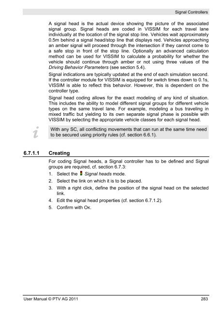
- Page 281: Merging section in Normal display M
- Page 285 and 286: 6.7.1.3 Editing 1. Select the Signa
- Page 287 and 288: [ACTIVATION] ● Vehicle Classes: T
- Page 289 and 290: 6.7.2.4 Editing Signal Controllers
- Page 291 and 292: [SIGTIMTBL. CFG] [SC/DET. REC] Sign
- Page 293 and 294: Signal Controllers Some of the gene
- Page 295 and 296: Signal Controllers Users of the Ext
- Page 297 and 298: Properties & Options Signal Control
- Page 299 and 300: Signal Controllers ► Start the au
- Page 301 and 302: The Menus FILE General data file ma
- Page 303 and 304: Signal Controllers Export parameter
- Page 305 and 306: Signal state sequence State Green F
- Page 307 and 308: Signal Controllers In the editing v
- Page 309 and 310: Signal Controllers Marking a cell i
- Page 311 and 312: Signal Controllers ● Pseudo stage
- Page 313 and 314: 6.7.4.5 Editing Stage Sequences (VI
- Page 315 and 316: Signal Controllers Double-click a s
- Page 317 and 318: Signal Controllers The list called
- Page 319 and 320: A second green time can only be def
- Page 321 and 322: Stretch or compress a signal progra
- Page 323 and 324: Zoom in the signal program display
- Page 325 and 326: Signal Controllers - CLASSICAL - 3D
- Page 327 and 328: Signal Controllers By means of dail
- Page 329 and 330: 6.7.4.9 Detecting Inconsistent Plan
- Page 331 and 332: Signal Controllers diverging stages
- Page 333 and 334:
3. Click the EXPORT command in the
- Page 335 and 336:
Signal Controllers The Excel file i
- Page 337:
Signal Controllers SIGNAL_HEAD 912
- Page 340 and 341:
7 Simulation of Pedestrians For pra
- Page 342 and 343:
7 Simulation of Pedestrians If the
- Page 344 and 345:
7 Simulation of Pedestrians 3D Mode
- Page 346 and 347:
7 Simulation of Pedestrians 7.1.4.1
- Page 348 and 349:
7 Simulation of Pedestrians The pro
- Page 350 and 351:
7 Simulation of Pedestrians ● Beh
- Page 352 and 353:
7 Simulation of Pedestrians 7.1.4.5
- Page 354 and 355:
7 Simulation of Pedestrians [IN- ST
- Page 356 and 357:
7 Simulation of Pedestrians Select
- Page 358 and 359:
7 Simulation of Pedestrians In orde
- Page 360 and 361:
7 Simulation of Pedestrians Signal-
- Page 362 and 363:
7 Simulation of Pedestrians Case 2:
- Page 364 and 365:
7 Simulation of Pedestrians 7.1.5.1
- Page 366 and 367:
7 Simulation of Pedestrians 7.1.6 P
- Page 368 and 369:
7 Simulation of Pedestrians Define
- Page 370 and 371:
7 Simulation of Pedestrians All cha
- Page 372 and 373:
7 Simulation of Pedestrians Pedestr
- Page 374 and 375:
7 Simulation of Pedestrians Method
- Page 376 and 377:
7 Simulation of Pedestrians pedestr
- Page 378 and 379:
7 Simulation of Pedestrians In fact
- Page 380 and 381:
7 Simulation of Pedestrians 6. Furt
- Page 382 and 383:
7 Simulation of Pedestrians Static
- Page 384 and 385:
7 Simulation of Pedestrians List of
- Page 386 and 387:
7 Simulation of Pedestrians All rou
- Page 388 and 389:
7 Simulation of Pedestrians number
- Page 390 and 391:
7 Simulation of Pedestrians In this
- Page 392 and 393:
7 Simulation of Pedestrians Display
- Page 394 and 395:
7 Simulation of Pedestrians The par
- Page 396 and 397:
7 Simulation of Pedestrians Add par
- Page 398 and 399:
7 Simulation of Pedestrians 7.2 Eva
- Page 400 and 401:
7 Simulation of Pedestrians Results
- Page 402 and 403:
7 Simulation of Pedestrians 2. Clic
- Page 404 and 405:
7 Simulation of Pedestrians - For s
- Page 406 and 407:
7 Simulation of Pedestrians v : Spe
- Page 408 and 409:
7 Simulation of Pedestrians Column
- Page 410 and 411:
7 Simulation of Pedestrians The fil
- Page 412 and 413:
7 Simulation of Pedestrians Paramet
- Page 414 and 415:
7 Simulation of Pedestrians If a qu
- Page 416 and 417:
7 Simulation of Pedestrians 7.2.5 P
- Page 418 and 419:
7 Simulation of Pedestrians The fol
- Page 420 and 421:
7 Simulation of Pedestrians Scheme
- Page 422 and 423:
7 Simulation of Pedestrians - be ov
- Page 424 and 425:
7 Simulation of Pedestrians Example
- Page 426 and 427:
7 Simulation of Pedestrians 7.5 Sim
- Page 428 and 429:
7 Simulation of Pedestrians As for
- Page 430 and 431:
7 Simulation of Pedestrians ► tau
- Page 432 and 433:
7 Simulation of Pedestrians In the
- Page 434 and 435:
7 Simulation of Pedestrians 7.7 Fie
- Page 436 and 437:
7 Simulation of Pedestrians 7.7.1 O
- Page 438 and 439:
7 Simulation of Pedestrians 7.7.2 S
- Page 440 and 441:
7 Simulation of Pedestrians 3. Crea
- Page 442 and 443:
7 Simulation of Pedestrians 6. Edit
- Page 444 and 445:
7 Simulation of Pedestrians 8. Crea
- Page 446 and 447:
7 Simulation of Pedestrians 10. Cre
- Page 449 and 450:
8 Simulation and Test The parameter
- Page 451 and 452:
● Comment: Text to identify the s
- Page 453 and 454:
Simulation of Vehicles and Pedestri
- Page 455 and 456:
Properties & Options Simulation of
- Page 457 and 458:
Test of Signal Control without Traf
- Page 459 and 460:
Test of Signal Control without Traf
- Page 461 and 462:
Test of Signal Control without Traf
- Page 463 and 464:
8.2.3.2 Green Time Statistics (*.AG
- Page 465 and 466:
9 Presentation For presentiations,
- Page 467 and 468:
Animation If option Save vehicle/p
- Page 469 and 470:
9.2 Recording 3D Video files Record
- Page 471 and 472:
Recording 3D Video files - A sinus-
- Page 473 and 474:
Recording 3D Video files All change
- Page 475 and 476:
10 Output of Results VISSIM offers
- Page 477 and 478:
Evaluation type Analyzer database S
- Page 479 and 480:
► SIGNAL CHANGES: Displays a chro
- Page 481 and 482:
Enabling Evaluations The filenames
- Page 483 and 484:
MS Access can only be applied to th
- Page 485 and 486:
► Travel Times (raw data): cf. se
- Page 487 and 488:
Example Runtime Messages steps perf
- Page 489 and 490:
[ACTIONS] Runtime Messages ● STAR
- Page 491 and 492:
[VERSIONS] Runtime Messages In cert
- Page 493:
Runtime Messages For some errors, a
- Page 496 and 497:
11 Evaluation Types for Simulations
- Page 498 and 499:
11 Evaluation Types for Simulations
- Page 500 and 501:
11 Evaluation Types for Simulations
- Page 502 and 503:
11 Evaluation Types for Simulations
- Page 504 and 505:
11 Evaluation Types for Simulations
- Page 506 and 507:
11 Evaluation Types for Simulations
- Page 508 and 509:
11 Evaluation Types for Simulations
- Page 510 and 511:
11 Evaluation Types for Simulations
- Page 512 and 513:
11 Evaluation Types for Simulations
- Page 514 and 515:
11 Evaluation Types for Simulations
- Page 516 and 517:
11 Evaluation Types for Simulations
- Page 518 and 519:
11 Evaluation Types for Simulations
- Page 520 and 521:
11 Evaluation Types for Simulations
- Page 522 and 523:
11 Evaluation Types for Simulations
- Page 524 and 525:
11 Evaluation Types for Simulations
- Page 526 and 527:
11 Evaluation Types for Simulations
- Page 528 and 529:
11 Evaluation Types for Simulations
- Page 530 and 531:
11 Evaluation Types for Simulations
- Page 532 and 533:
11 Evaluation Types for Simulations
- Page 534 and 535:
11 Evaluation Types for Simulations
- Page 536 and 537:
11 Evaluation Types for Simulations
- Page 538 and 539:
11 Evaluation Types for Simulations
- Page 540 and 541:
11 Evaluation Types for Simulations
- Page 542 and 543:
11 Evaluation Types for Simulations
- Page 544 and 545:
11 Evaluation Types for Simulations
- Page 546 and 547:
11 Evaluation Types for Simulations
- Page 548 and 549:
11 Evaluation Types for Simulations
- Page 550 and 551:
11 Evaluation Types for Simulations
- Page 552 and 553:
11 Evaluation Types for Simulations
- Page 554 and 555:
11 Evaluation Types for Simulations
- Page 556 and 557:
11 Evaluation Types for Simulations
- Page 558 and 559:
11 Evaluation Types for Simulations
- Page 560 and 561:
11 Evaluation Types for Simulations
- Page 562 and 563:
11 Evaluation Types for Simulations
- Page 564 and 565:
11 Evaluation Types for Simulations
- Page 566 and 567:
11 Evaluation Types for Simulations
- Page 568 and 569:
11 Evaluation Types for Simulations
- Page 570 and 571:
11 Evaluation Types for Simulations
- Page 572 and 573:
11 Evaluation Types for Simulations
- Page 574 and 575:
11 Evaluation Types for Simulations
- Page 576 and 577:
11 Evaluation Types for Simulations
- Page 578 and 579:
11 Evaluation Types for Simulations
- Page 580 and 581:
11 Evaluation Types for Simulations
- Page 582 and 583:
11 Evaluation Types for Simulations
- Page 584 and 585:
11 Evaluation Types for Simulations
- Page 586 and 587:
11 Evaluation Types for Simulations
- Page 588 and 589:
11 Evaluation Types for Simulations
- Page 590 and 591:
11 Evaluation Types for Simulations
- Page 592 and 593:
12 Dynamic Assignment 12.1 Introduc
- Page 594 and 595:
12 Dynamic Assignment Example: If w
- Page 596 and 597:
12 Dynamic Assignment 12.3 Building
- Page 598 and 599:
12 Dynamic Assignment [DYNAMIC ASSI
- Page 600 and 601:
12 Dynamic Assignment Right clickin
- Page 602 and 603:
12 Dynamic Assignment You may conve
- Page 604 and 605:
12 Dynamic Assignment Multi Selecti
- Page 606 and 607:
12 Dynamic Assignment Edit data Con
- Page 608 and 609:
12 Dynamic Assignment Manual adjust
- Page 610 and 611:
12 Dynamic Assignment Edge attribut
- Page 612 and 613:
12 Dynamic Assignment 1. To open th
- Page 614 and 615:
12 Dynamic Assignment The buttons s
- Page 616 and 617:
12 Dynamic Assignment Matrix file f
- Page 618 and 619:
12 Dynamic Assignment ► With data
- Page 620 and 621:
12 Dynamic Assignment 12.5 Simulate
- Page 622 and 623:
12 Dynamic Assignment TO n, κ i =
- Page 624 and 625:
12 Dynamic Assignment 12.6 Route Se
- Page 626 and 627:
12 Dynamic Assignment Again the sen
- Page 628 and 629:
12 Dynamic Assignment ALTERNATIVE P
- Page 630 and 631:
12 Dynamic Assignment 12.7 Optional
- Page 632 and 633:
12 Dynamic Assignment average of th
- Page 634 and 635:
12 Dynamic Assignment However, the
- Page 636 and 637:
12 Dynamic Assignment Other than dy
- Page 638 and 639:
12 Dynamic Assignment 2. Increase t
- Page 640 and 641:
12 Dynamic Assignment in VISSIM can
- Page 642 and 643:
12 Dynamic Assignment ● Search p
- Page 644 and 645:
12 Dynamic Assignment - The identif
- Page 646 and 647:
12 Dynamic Assignment ● Archive
- Page 648 and 649:
12 Dynamic Assignment 12.9 Initial
- Page 650 and 651:
12 Dynamic Assignment For more deta
- Page 652 and 653:
12 Dynamic Assignment 3. Select opt
- Page 654 and 655:
13 VISSIM Programming Interfaces (A
- Page 656 and 657:
13 VISSIM Programming Interfaces (A
- Page 658 and 659:
13 VISSIM Programming Interfaces (A
- Page 660 and 661:
13 VISSIM Programming Interfaces (A
- Page 662 and 663:
14 Glossary of Files associated wit
- Page 664 and 665:
14 Glossary of Files associated wit
- Page 666 and 667:
14 Glossary of Files associated wit
- Page 668 and 669:
14 Glossary of Files associated wit
- Page 670 and 671:
14 Glossary of Files associated wit
- Page 672 and 673:
15 Service & Support 15.1 Online He
- Page 674 and 675:
15 Service & Support [SEARCH] Full-
- Page 676 and 677:
15 Service & Support - one of the h
- Page 678 and 679:
15 Service & Support 15.3 Contact I
- Page 680:
15 Service & Support 15.4 Services