SIREC D Display Recorder 7ND4000
SIREC D Display Recorder 7ND4000
SIREC D Display Recorder 7ND4000

Sie wollen auch ein ePaper? Erhöhen Sie die Reichweite Ihrer Titel.
YUMPU macht aus Druck-PDFs automatisch weboptimierte ePaper, die Google liebt.
General Description<br />
1.2 RECORDER DESCRIP-<br />
TION<br />
1.2.1 General. The <strong>SIREC</strong> D <strong>Display</strong> <strong>Recorder</strong><br />
is a Paperless Recording instrument that<br />
stores it’s data in internal memory and on either a<br />
3½ inch (89 mm) floppy disk or an industrystandard<br />
removable PCMCIA memory card. All<br />
data is stored in MSDOS format and may be archived<br />
or analyzed on any IBM compatible PC<br />
running Microsoft’s Windows 3.1 or Windows 95<br />
using the available Companion software. The instrument<br />
retains all the features of a traditional<br />
Paper Chart <strong>Recorder</strong> by virtue of its large Liquid<br />
Crystal <strong>Display</strong> (LCD) which presents the data in<br />
the traditional chart mode as well as in bar graph or<br />
digital numeric form.<br />
The unit has many features and functions which<br />
are unique and cannot be performed on traditional<br />
paper recorders such as data compression and<br />
historic data browsing. The recorder is programmed<br />
via the LCD display which is also a touch<br />
sensitive keypad.<br />
1.2.2 Inputs. The recorder will measure and<br />
process up to 12 direct inputs. If direct inputs are<br />
not desired, the <strong>Display</strong> <strong>Recorder</strong> will accept up to<br />
twelve points from a combination of calculated,<br />
conditional, or external point types.<br />
Direct input sources may come from voltage, current,<br />
dry contacts, thermocouple, or RTD sources.<br />
The voltage and current ranges accepted by the<br />
instrument include: 0 to ±100mV, 0 to ±1 Volt, and<br />
0 to ±10 Volts; 4 to 20 and 10 to 50mA current<br />
(using an internally switched 50 ohm shunt). Thermocouple<br />
inputs include B, C, E, J, K, R, S, T,<br />
Nickel/Nickel Moly, and Nicrosil-Nisil. RTD inputs<br />
accepted include 10 ohm Cu, 100 ohm Platinum,<br />
200 ohm Platinum and 120 ohm Nickel.<br />
1.2.3 Instrument Size. The instrument is<br />
sized to fit in a DIN standard panel cutout of<br />
138mm x 138mm (5.43 inches x 5.43 inches) and<br />
requires only 21.6 cm (8½ inches) behind panel<br />
depth. Actual dimensions of the instrument are<br />
shown in Figure 2-1 <strong>Recorder</strong> Dimensions, in<br />
Chapter 2 of this manual.<br />
1.2.4 Menus. The instrument’s features are<br />
accessed through a series of menus. These menus<br />
are accessed via a command button bar which is<br />
initiated by pressing the MENU button displayed in<br />
the bottom right hand corner of the LCD screen.<br />
There is also a STATUS bar or line along the top of<br />
the screen which can be used to display various<br />
recorder parameters. (Refer to Section 3.1). The<br />
Command button bar contains three user pro-<br />
1-2<br />
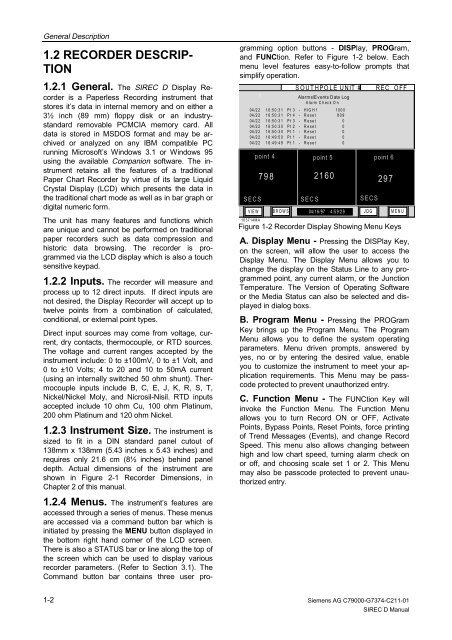
gramming option buttons - DISPlay, PROGram,<br />
and FUNCtion. Refer to Figure 1-2 below. Each<br />
menu level features easy-to-follow prompts that<br />
simplify operation.<br />
SOUTHPOLE UNIT #6 REC OFF<br />
1 Alarms/Events Data Log<br />
Alarm Check On<br />
04 /2 2 1 6 :5 0 :3 1 P t 3 - H IG H 1 10 0 0<br />
04 /2 2 1 6 :5 0 :3 1 P t 4 - R e s e t 8 0 9<br />
04 /2 2 1 6 :5 0 :3 1 P t 3 - R e s e t 0<br />
04 /2 2 1 6 :5 0 :3 0 P t 2 - R e s e t 0<br />
04 /2 2 1 6 :5 0 :3 0 P t 1 - R e s e t 0<br />
04 /2 2 1 6 :4 9 :5 0 P t 1 - R e s e t 0<br />
04 /2 2 1 6 :4 9 :4 9 P t 1 - R e s e t 0<br />
point 4 point 5 point 6<br />
798 2160 297<br />
SECS SECS SECS<br />
V IE W<br />
103714MA<br />
B R O W S 04/ 16 /97 4 :5 9:2 9 J O G M E N U<br />
Figure 1-2 <strong>Recorder</strong> <strong>Display</strong> Showing Menu Keys<br />
A. <strong>Display</strong> Menu - Pressing the DISPlay Key,<br />
on the screen, will allow the user to access the<br />
<strong>Display</strong> Menu. The <strong>Display</strong> Menu allows you to<br />
change the display on the Status Line to any programmed<br />
point, any current alarm, or the Junction<br />
Temperature. The Version of Operating Software<br />
or the Media Status can also be selected and displayed<br />
in dialog boxs.<br />
B. Program Menu - Pressing the PROGram<br />
Key brings up the Program Menu. The Program<br />
Menu allows you to define the system operating<br />
parameters. Menu driven prompts, answered by<br />
yes, no or by entering the desired value, enable<br />
you to customize the instrument to meet your application<br />
requirements. This Menu may be passcode<br />
protected to prevent unauthorized entry.<br />
C. Function Menu - The FUNCtion Key will<br />
invoke the Function Menu. The Function Menu<br />
allows you to turn Record ON or OFF, Activate<br />
Points, Bypass Points, Reset Points, force printing<br />
of Trend Messages (Events), and change Record<br />
Speed. This menu also allows changing between<br />
high and low chart speed, turning alarm check on<br />
or off, and choosing scale set 1 or 2. This Menu<br />
may also be passcode protected to prevent unauthorized<br />
entry.<br />
Siemens AG C79000-G7374-C211-01<br />
<strong>SIREC</strong> D Manual