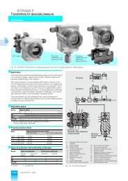
SIREC D Display Recorder 7ND4000
SIREC D Display Recorder 7ND4000
SIREC D Display Recorder 7ND4000

Erfolgreiche ePaper selbst erstellen
Machen Sie aus Ihren PDF Publikationen ein blätterbares Flipbook mit unserer einzigartigen Google optimierten e-Paper Software.
Programming<br />
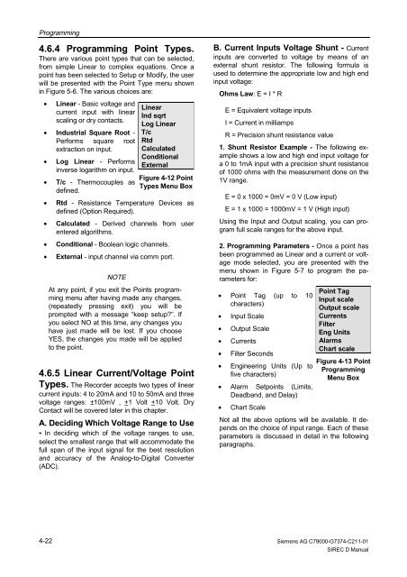
4.6.4 Programming Point Types.<br />
There are various point types that can be selected,<br />
from simple Linear to complex equations. Once a<br />
point has been selected to Setup or Modify, the user<br />
will be presented with the Point Type menu shown<br />
in Figure 5-6. The various choices are:<br />
• Linear - Basic voltage and<br />
current input with linear<br />
scaling or dry contacts.<br />
• Industrial Square Root -<br />
Performs square root<br />
extraction on input.<br />
• Log Linear - Performs<br />
inverse logarithm on input.<br />
• T/c - Thermocouples as<br />
defined.<br />
• Rtd - Resistance Temperature Devices as<br />
defined (Option Required).<br />
• Calculated - Derived channels from user<br />
entered algorithms.<br />
• Conditional - Boolean logic channels.<br />
• External - input channel via comm port.<br />
4-22<br />
NOTE<br />
Linear<br />
Ind sqrt<br />
Log Linear<br />
T/c<br />
Rtd<br />
Calculated<br />
Conditional<br />
External<br />
Figure 4-12 Point<br />
Types Menu Box<br />
At any point, if you exit the Points programming<br />
menu after having made any changes,<br />
(repeatedly pressing exit) you will be<br />
prompted with a message “keep setup?”. If<br />
you select NO at this time, any changes you<br />
have just made will be lost. If you choose<br />
YES, the changes you made will be applied<br />
to the point.<br />
4.6.5 Linear Current/Voltage Point<br />
Types. The <strong>Recorder</strong> accepts two types of linear<br />
current inputs: 4 to 20mA and 10 to 50mA and three<br />
voltage ranges: ±100mV , +1 Volt +10 Volt. Dry<br />
Contact will be covered later in this chapter.<br />
A. Deciding Which Voltage Range to Use<br />
- In deciding which of the voltage ranges to use,<br />
select the smallest range that will accommodate the<br />
full span of the input signal for the best resolution<br />
and accuracy of the Analog-to-Digital Converter<br />
(ADC).<br />
B. Current Inputs Voltage Shunt - Current<br />
inputs are converted to voltage by means of an<br />
external shunt resistor. The following formula is<br />
used to determine the appropriate low and high end<br />
input voltage:<br />
Ohms Law: E = I * R<br />
E = Equivalent voltage inputs<br />
I = Current in milliamps<br />
R = Precision shunt resistance value<br />
1. Shunt Resistor Example - The following example<br />
shows a low and high end input voltage for<br />
a 0 to 1mA input with a precision shunt resistance<br />
of 1000 ohms with the measurement done on the<br />
1V range.<br />
E = 0 x 1000 = 0mV = 0 V (Low input)<br />
E = 1 x 1000 = 1000mV = 1 V (High input)<br />
Using the Input and Output scaling, you can program<br />
full scale ranges for the above input.<br />
2. Programming Parameters - Once a point has<br />
been programmed as Linear and a current or voltage<br />
mode selected, you are presented with the<br />
menu shown in Figure 5-7 to program the parameters<br />
for:<br />
• Point Tag (up to 10<br />
characters)<br />
• Input Scale<br />
• Output Scale<br />
• Currents<br />
• Filter Seconds<br />
• Engineering Units (Up to<br />
five characters)<br />
• Alarm Setpoints (Limits,<br />
Deadband, and Delay)<br />
Point Tag<br />
Input scale<br />
Output scale<br />
Currents<br />
Filter<br />
Eng Units<br />
Alarms<br />
Chart scale<br />
Figure 4-13 Point<br />
Programming<br />
Menu Box<br />
• Chart Scale<br />
Not all the above options will be available. It depends<br />
on the choice of input range. Each of these<br />
parameters is discussed in detail in the following<br />
paragraphs.<br />
Siemens AG C79000-G7374-C211-01<br />
<strong>SIREC</strong> D Manual