SIREC D Display Recorder 7ND4000
SIREC D Display Recorder 7ND4000
SIREC D Display Recorder 7ND4000
Erfolgreiche ePaper selbst erstellen
Machen Sie aus Ihren PDF Publikationen ein blätterbares Flipbook mit unserer einzigartigen Google optimierten e-Paper Software.
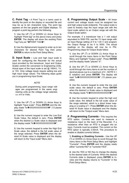
C. Point Tag - A Point Tag is a name used to<br />
identify the point on the display or recorded file and<br />
may be up to ten characters long. The point tag<br />
appears on the bar graphs and Digital displays. To<br />
program a point tag perform the following:<br />
1. Use the UP (↑) or DOWN (↓) Arrow Keys to<br />
highlight “Point tag" on the above menu and press<br />
ENTER. The display will show the existing Point<br />
Tag if any as "�POINT TAG�“.<br />
2. Use the Alphanumeric keypad to enter up to ten<br />
characters for desired Point Tag then press<br />
ENTER to return to the Point Setup Menu.<br />
D. Input Scale - Low and high input scale is<br />
used for configuring the <strong>Recorder</strong> for the actual<br />
input provided by the transducer. Input and Output<br />
Scales control the conversion to Engineering Units.<br />
Actual span of the input scale is set @ 180mV, 1V,<br />
or 10V. Only voltage inputs require setting low and<br />
high input range values. The following steps guide<br />
you in programming Input Scale:<br />
NOTE<br />
During point programming, input range voltages<br />
are programmed in the same engineering<br />
units as the voltage range selected,<br />
i.e. mV or Volts.<br />
1. Use the UP (↑) or DOWN (↓) Arrow Keys to<br />
highlight "Input scale". Press ENTER and the display<br />
reads "lo�XXXXXXXXXXXXX�” (13 places<br />
possible).<br />
2. Use the numeric keypad to enter the Low End<br />
Scale Value, the default is zero. Press ENTER<br />
when the desired Lo Scale value is displayed and<br />
the display reads "hi�XXXXXXXXXXXXX�".<br />
3. Use the numeric keypad to enter the High End<br />
Scale value, the default is the full scale value of<br />
the range selected. Press ENTER when the desired<br />
Hi Scale value is displayed and the display<br />
will return to the "Input scale" Menu item.<br />
Siemens AG C79000-G7374-C211-01<br />
<strong>SIREC</strong> D Manual<br />
Programming<br />
E. Programming Output Scale - All linear<br />
current and voltage inputs must be assigned low<br />
and high output scale endpoints. The output scale is<br />
used to linearly map the input range (set with the<br />
Input scale option) to an Output range set with the<br />
Output Scale option.<br />
For example, if a transducer has a 1 volt output<br />
equivalent to 5000 PSI, use the 1V input range with<br />
an Input Range setting of 0 to 1.00 V and program<br />
the Output Range to be 0 to 5000. The actual<br />
readings on the display will now be in PSI.<br />
Programming steps for Output Scale follow:<br />
1. Use the UP (↑) or DOWN (↓) Arrow Keys to<br />
scroll through the menu items in the Point Setup<br />
Menu and highlight "Output scale". Press ENTER<br />
and the display reads "places? X".<br />
2. Use the UP (↑) or DOWN (↓) Arrow Keys to<br />
scroll through the menu items to set the number of<br />
decimal places (up to a maximum of 4 - NOTE 5 =<br />
E notation) and press ENTER. The display will<br />
read "lo�XXXXXXXXXXXXX�” (13 places possible).<br />
3. Use the numeric keypad to enter the low end<br />
scale value, the default is zero. Press ENTER<br />
when the desired Lo Scale value is displayed and<br />
the display reads "hi�XXXXXXXXXXXXX�".<br />
4. Use the numeric keypad to enter the high end<br />
scale value, the default is the full scale value of<br />
the range selected, which is a direct linear mapping<br />
or a scaling of 1. Press ENTER when the desired<br />
Hi Scale value is displayed and the display<br />
will return to the "Output scale" Menu item.<br />
F. Programming Currents - This requires the<br />
RTD option. Currents are used to measure a<br />
resistance input on the back of the <strong>Recorder</strong>. If a<br />
resistance other than an RTD is plugged into an<br />
input, Currents must be enabled. The current on the<br />
RTD option is typically 2.00mA. The procedure to<br />
enable or disable currents follows.<br />
1. Enabling or Disabling Currents - Use the UP<br />
(↑) or DOWN (↓) Arrow Keys to scroll through the<br />
menu items in the Point Setup Menu and highlight<br />
"Currents". Press ENTER and the display reads<br />
either "currents=NO" or "currents=YES".<br />
2. Use the YES or NO Key to change the display<br />
to the desired state of Currents. When the desired<br />
Currents state is displayed, press ENTER to invoke<br />
and the display returns to "Currents" in the<br />
Point Setup Menu.<br />
4-23


