SIREC D Display Recorder 7ND4000
SIREC D Display Recorder 7ND4000
SIREC D Display Recorder 7ND4000

Sie wollen auch ein ePaper? Erhöhen Sie die Reichweite Ihrer Titel.
YUMPU macht aus Druck-PDFs automatisch weboptimierte ePaper, die Google liebt.
Digital Inputs (External Switches)<br />
All 3 inputs= Set to Events mode<br />
All Event Messages= Set to spaces (cleared)<br />
<strong>Recorder</strong><br />
Record = Off<br />
Record Speed = 4 samples/sec.<br />
Record Mode = Fill to end<br />
Pens = None<br />
Record Data, Alarms = Off<br />
File Name<br />
File Name = SWRevNo<br />
(Software Revision Number)<br />
3.3 CONTROLS AND<br />
DISPLAYS<br />
3.3.1 General. The following paragraphs are<br />
intended to familiarize the operator with the <strong>Display</strong><br />
Screen, and the commands initiated from the<br />
Touch-keys on the Screen. The <strong>Recorder</strong> has an<br />
LCD Graphics Screen that also acts as a touch<br />
keypad. Areas of the screen are active as push<br />
buttons, the exact areas which are sensitive depends<br />
on what is currently displayed.<br />
You have only to lightly touch the screen area de-<br />
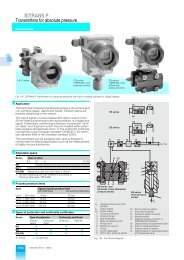
SIEMENS <strong>SIREC</strong> D<br />
1036 99MA<br />
SOUTHPOLE UNIT #6 REC OFF<br />
1 2 3 4<br />
5 6<br />
1 B G R=2 P O IN T<br />
GRAPHICS AREA<br />
0.0 300.0 600.0<br />
VIEW BROW S 04/16/97 4:59:29 JO G ME NU<br />
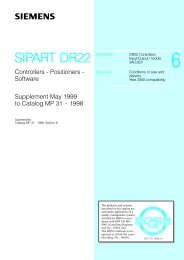
Figure 3-1 <strong>Recorder</strong> and Screen<br />
picting the button to activate the function. If the<br />
buzzer is turned on, the unit will provide audible<br />
feedback, as a short beep, each time a “button”<br />
press is registered. The default display is shown in<br />
Figure 3-1. Commands initiated from the keyboard<br />
activate direct functions or enable access to various<br />
menus and prompts. A definition of each<br />
Siemens AG C79000-G7374-C211-01<br />
<strong>SIREC</strong> D Manual<br />
Operation<br />
Touch-key and its capabilities follows. It is necessary<br />
to view the screen head on to avoid parallax<br />
error when trying to press buttons which are close<br />
together, and accidentally pressing the wrong area<br />
of the screen. At any point you can return to the<br />
active viewing mode by continuing to press the<br />
EXIT button until it returns to MENU status.<br />
3.3.2 Front Panel Color Screen. The<br />
screen is divided into three distinct areas, the<br />
BUTTON BAR, along the bottom of the screen<br />
(containing the time / date stamp), the STATUS<br />
LINE, across the top of the screen, and the<br />
GRAPHICS AREA between them. Each area is<br />
used to present different information. The default<br />
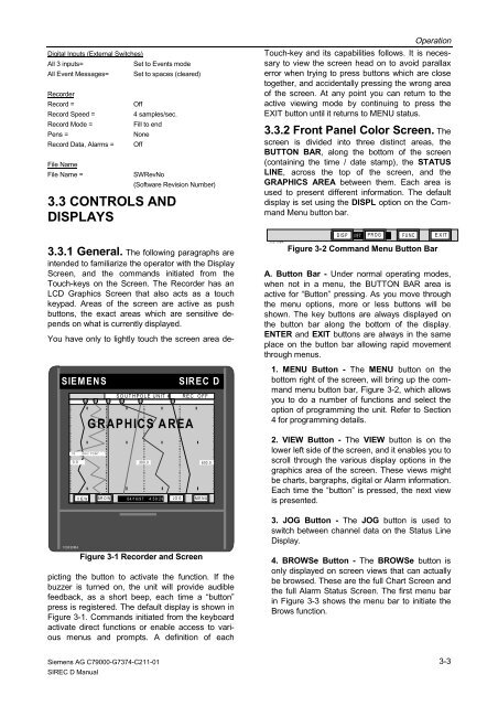
display is set using the DISPL option on the Command<br />
Menu button bar.<br />
103715MA<br />
DISP 04/16/97 4:59:29 PROG<br />
FUNC EXIT<br />
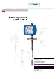
Figure 3-2 Command Menu Button Bar<br />
A. Button Bar - Under normal operating modes,<br />
when not in a menu, the BUTTON BAR area is<br />
active for “Button” pressing. As you move through<br />
the menu options, more or less buttons will be<br />
shown. The key buttons are always displayed on<br />
the button bar along the bottom of the display.<br />
ENTER and EXIT buttons are always in the same<br />
place on the button bar allowing rapid movement<br />
through menus.<br />
1. MENU Button - The MENU button on the<br />
bottom right of the screen, will bring up the command<br />
menu button bar, Figure 3-2, which allows<br />
you to do a number of functions and select the<br />
option of programming the unit. Refer to Section<br />
4 for programming details.<br />
2. VIEW Button - The VIEW button is on the<br />
lower left side of the screen, and it enables you to<br />
scroll through the various display options in the<br />
graphics area of the screen. These views might<br />
be charts, bargraphs, digital or Alarm information.<br />
Each time the “button” is pressed, the next view<br />
is presented.<br />
3. JOG Button - The JOG button is used to<br />
switch between channel data on the Status Line<br />
<strong>Display</strong>.<br />
4. BROWSe Button - The BROWSe button is<br />
only displayed on screen views that can actually<br />
be browsed. These are the full Chart Screen and<br />
the full Alarm Status Screen. The first menu bar<br />
in Figure 3-3 shows the menu bar to initiate the<br />
Brows function.<br />
3-3