SIREC D Display Recorder 7ND4000
SIREC D Display Recorder 7ND4000
SIREC D Display Recorder 7ND4000

Erfolgreiche ePaper selbst erstellen
Machen Sie aus Ihren PDF Publikationen ein blätterbares Flipbook mit unserer einzigartigen Google optimierten e-Paper Software.
Installation and Wiring<br />
103690MA<br />
2.2.3 Panel Mounting - The instrument is<br />
sized to fit in a DIN standard panel cutout of<br />
138mm x 138mm (5.43 inches x 5.43 inches) and<br />
requires only 21.6 cm (8½ inches) behind panel<br />
depth. Actual dimensions of the instrument are<br />
shown in Figure 2-1. The recorder should be<br />
mounted in a vertical panel to ensure proper<br />
operation. Ensure that you have the proper<br />
clearances and proceed as follows:<br />
A. Cutout Size - Cut a panel opening 138mm x<br />
138mm (5.43 x 5.43 inches) in the location desired.<br />
Refer to drawing DM100162 in Chapter 8 of this<br />
Manual.<br />
B. Handling - Remove any packaging material<br />
from the recorder. Always handle the unit carefully<br />
to avoid damaging the LCD display or scratching<br />
the display surface.<br />
2-2<br />
5.67 (144)<br />
5.67 (144)<br />
1.20 (30)<br />
NOTE: Dimensions are in inches (M illim eters)<br />
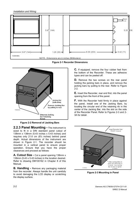
Figure 2-2 Removal of Jacking Bars<br />
Figure 2-1 <strong>Recorder</strong> Dimensions<br />
8.00 (203)<br />
Power<br />
Cord<br />
0.42 (11)<br />
C. If equipped, remove the four rubber feet from<br />
the bottom of the <strong>Recorder</strong>. These are adhesive<br />
types and can be peeled off.<br />
D. Remove the two screws on the rear panel<br />
holding the jacking bars in place, and remove the<br />
jacking bars by pulling to the rear. Refer to Figure<br />
2-2.<br />
E. Insert the <strong>Recorder</strong>, rear end first, into the panel<br />
opening from the front of the panel.<br />
F. With the <strong>Recorder</strong> held firmly in place against<br />
the panel, install one of the Jacking Bars, by<br />
locating the circular end of the retaining rib in the<br />
center of the Jacking Bar, into the slot on the side<br />
of the <strong>Recorder</strong> Panel. Refer to Figures 2-3 and 2-<br />
3A for detail.<br />
103692MA<br />
Insert <strong>Recorder</strong> from<br />
FRONT of panel.<br />
Slide Jacking Bars in<br />
place once <strong>Recorder</strong> is<br />
in panel. Use Jacking<br />
Bar Screws to tighten<br />
in pla ce .<br />
Figure 2-3 Mounting in Panel<br />
Siemens AG C79000-G7374-C211-01<br />
<strong>SIREC</strong> D Manual<br />
5.35 (136