SIREC D Display Recorder 7ND4000
SIREC D Display Recorder 7ND4000
SIREC D Display Recorder 7ND4000

Sie wollen auch ein ePaper? Erhöhen Sie die Reichweite Ihrer Titel.
YUMPU macht aus Druck-PDFs automatisch weboptimierte ePaper, die Google liebt.
CH6 CH5<br />
NO C NC NO C NC<br />
103696MA<br />
G. Linear Inputs - Linear inputs consist of<br />
current inputs (4-20 milliamps or 10 to 50<br />
milliamps) or variable voltage input ranges (+100<br />
millivolts, +1 volt, +10 volt, and normally<br />
open/closed contact inputs). Connect CURRENT<br />
and VOLTAGE inputs as shown in view of Figure<br />
2-7 labeled “VOLTS OR mA”.<br />
NOTE<br />
For current inputs, an external precision resistor<br />
will need to be connected across the<br />
input terminal blocks. An internal resistor is<br />
not available.<br />
NOTE<br />
Signal inputs greater than 10 volts require<br />
the use of an input voltage divider (consult<br />
your local representative or the factory).<br />
2.3.4 Relay Output, Contact Input<br />
(Option) - The <strong>Recorder</strong> may be equipped<br />
with an optional Digital Input Output Board (Part<br />
No. 5380-316) which has six potential free, Form<br />
C, relay contacts and three opto-isolated digital<br />
inputs.<br />
WARNING<br />
TO PREVENT THE POSSIBILITY OF<br />
ELECTRICAL SHOCK, USE EXTREME<br />
CAUTION WHEN WIRING CONTACT<br />
OUTPUT CONNECTIONS. HAZARDOUS<br />
POTENTIALS MAY EXIST ON CONTACT<br />
OUTPUT TERMINALS WHICH ARE<br />
FLOATING WITH RESPECT TO<br />
INSTRUMENT GROUND. THESE<br />
Siemens AG C79000-G7374-C211-01<br />
<strong>SIREC</strong> D Manual<br />
R elay O utputs<br />
CH4<br />
NO C NC<br />
CH3<br />
NO C N C<br />
CH2<br />
NO C NC<br />
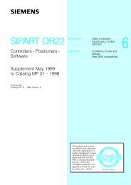
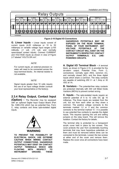
Figure 2-10 Digital I/O Connections<br />
CH1<br />
N O C N C<br />
Installation and Wiring<br />
INPUT<br />
3 2 1 C<br />
HAZARDOUS POTENTIALS MAY BE<br />
EXPOSED ON THE REAR TERMINAL<br />
PANEL OF YOUR INSTRUMENT. ANY<br />
VOLTAGE POTENTIALS AT THE<br />
CONTACT CIRCUIT WILL EXIST ON THE<br />
INSTRUMENT’S RESPECTIVE CONTACT<br />
OUTPUT TERMINALS; E.G. LINE-<br />
POWERED CIRCUITS.<br />
A. Digital I/O Terminal Block - A terminal<br />
block, as shown in Figure 2-10, is provided for the<br />
six-alarm output, Potential Free, Form C,<br />
connections: normally open (NO), common (C),<br />
and normally closed (NC), and the three digital<br />
inputs which share a common. The relay contacts<br />
are capable of switching 250 V~ at 1 Amp or 30<br />
VDC at 1A.<br />
B. Varistors - The potential-free relay contacts<br />
are protected internally with 300 volt Metal Oxide<br />
Varistors (MOVs) to prevent contact arcing.<br />
C. Inputs - The opto-isolated inputs require an<br />
external potential of 5 to 12 volts DC @ 10<br />
milliamps. The three inputs are isolated from the<br />
unit, but not from each other as they share a<br />
common. The positive voltage connects to the<br />
terminals marked 1,2 or 3 and the common<br />
connects to the terminal marked “C”. It is possible<br />
to use potential free contacts to operate the digital<br />
inputs. This requires opening the unit and setting<br />
jumpers on the relay board. This will remove the<br />
isolation. Contact the factory for details.<br />
The terminal strip is protected by a transparent<br />
acrylic cover held in place by two screws. This<br />
cover protects the user from accidentally touching<br />
terminals that may have hazardous potentials on<br />
them and must be removed before wires can be<br />
connected to the terminals. Loosen the two screws<br />
at either end of the cover and remove them.<br />
Replace the cover once all connections have been<br />
made.<br />
2-7