SIREC D Display Recorder 7ND4000
SIREC D Display Recorder 7ND4000
SIREC D Display Recorder 7ND4000

Erfolgreiche ePaper selbst erstellen
Machen Sie aus Ihren PDF Publikationen ein blätterbares Flipbook mit unserer einzigartigen Google optimierten e-Paper Software.
Installation and Wiring<br />
2-6<br />
CAUTION<br />
NEVER RUN SIGNAL AND POWER OR<br />
CONTROL WIRING TOGETHER IN THE<br />
SAME CONDUIT. THIS IS TO PREVENT<br />
POSSIBLE RECORDING ERRORS DUE<br />
TO INDUCED SIGNALS BETWEEN<br />
LINES. ROUTE SIGNAL WIRES AWAY<br />
FROM POWER WIRES AT THE REAR<br />
PANEL. GROUND CABLE SHIELDS AT<br />
ONE END ONLY TO ELIMINATE THE<br />
POSSIBILITY OF INTERFERENCE DUE<br />
TO GROUND LOOP CURRENTS. WHEN<br />
GROUNDED TRANSDUCERS ARE<br />
USED, THE SHIELD SHOULD BE<br />
GROUNDED AT THE SENSOR END<br />
ONLY.<br />
A. Type of Inputs - The standard <strong>Recorder</strong><br />
accepts up to six direct inputs depending on the<br />
options you ordered. Input connection is via screw<br />
terminal connectors on the rear panel. Inputs can<br />
be mixed in any combination of thermocouple, RTD<br />
(with the appropriate option), milliamps, millivolts,<br />
volts or contact inputs. As inputs are connected, it<br />
is recommended that you record the data on the<br />
Point Programming Chart.<br />
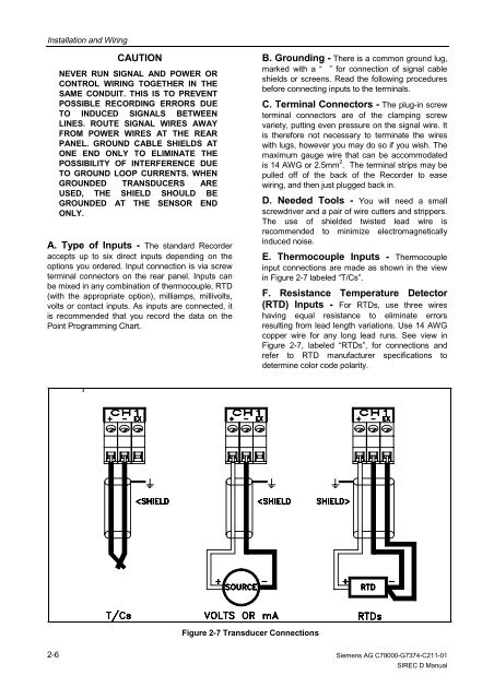
Figure 2-7 Transducer Connections<br />
B. Grounding - There is a common ground lug,<br />
marked with a “ ” for connection of signal cable<br />
shields or screens. Read the following procedures<br />
before connecting inputs to the terminals.<br />
C. Terminal Connectors - The plug-in screw<br />
terminal connectors are of the clamping screw<br />
variety, putting even pressure on the signal wire. It<br />
is therefore not necessary to terminate the wires<br />
with lugs, however you may do so if you wish. The<br />
maximum gauge wire that can be accommodated<br />
is 14 AWG or 2.5mm 2 . The terminal strips may be<br />
pulled off of the back of the <strong>Recorder</strong> to ease<br />
wiring, and then just plugged back in.<br />
D. Needed Tools - You will need a small<br />
screwdriver and a pair of wire cutters and strippers.<br />
The use of shielded twisted lead wire is<br />
recommended to minimize electromagnetically<br />
induced noise.<br />
E. Thermocouple Inputs - Thermocouple<br />
input connections are made as shown in the view<br />
in Figure 2-7 labeled “T/Cs”.<br />
F. Resistance Temperature Detector<br />
(RTD) Inputs - For RTDs, use three wires<br />
having equal resistance to eliminate errors<br />
resulting from lead length variations. Use 14 AWG<br />
copper wire for any long lead runs. See view in<br />
Figure 2-7, labeled “RTDs”, for connections and<br />
refer to RTD manufacturer specifications to<br />
determine color code polarity.<br />
Siemens AG C79000-G7374-C211-01<br />
<strong>SIREC</strong> D Manual