SIREC D Display Recorder 7ND4000
SIREC D Display Recorder 7ND4000
SIREC D Display Recorder 7ND4000

Sie wollen auch ein ePaper? Erhöhen Sie die Reichweite Ihrer Titel.
YUMPU macht aus Druck-PDFs automatisch weboptimierte ePaper, die Google liebt.
Installation and Wiring<br />
2.3.5 Serial Port - RS232 or<br />
RS485 (Option) - The recorder may be<br />
fitted with a serial communication option, either<br />
RS232 or RS485. The RS232 connection requires<br />
a standard DB9 Female connector and connects to<br />
an IBM PC compatible computer using a null<br />
modem cable and can support cable runs up to 50<br />
feet (16m). The RS485 connection is via two wire<br />
(twisted pair) cable and can support cable runs up<br />
to 4000 feet (1300m). The RS232 Connections to<br />
the DB9 female connector are as follows:<br />
Table 2-2 RS232 Connections<br />
2-8<br />
DB9<br />
Pin<br />
Connection<br />
Direction<br />
To<br />
Modem<br />
pin<br />
(DB25)<br />
To<br />
Computer<br />
(DB9)<br />
2 Rx Data In 3 3<br />
3 Tx Data Out 2 2<br />
5 Common Common 7 5<br />
7 RTS Out NC 8<br />
8 CTS In 4,5 7<br />
103697MA<br />
RS232<br />
2 - RxD<br />
3 - TxD<br />
5 - Com<br />
7 - RTS<br />
8 - CTS<br />
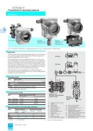
Figure 2-11 RS232 Interface Option<br />
A. Connecting RS232 to Remote<br />
Computer - When connecting to a remote<br />
computer, connect that computers RTS and CTS<br />
lines together and connect only pins 2,3 and 5 from<br />
the recorder. The recorder TxD line goes to the<br />
computer RxD line, and the recorder RxD line goes<br />
to the computer TxD line. The common is<br />
connected at both ends. A null modem cable with<br />
female connectors both ends can be used to<br />
connect the recorder to an IBM compatible<br />
Personal Computer. Connections to a modem are<br />
shown in Table 2-2. Figure 2-11 shows the RS232<br />
Interface option.<br />
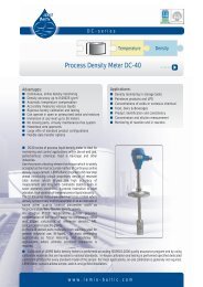
B. Connecting RS485 Terminal - The<br />
RS485 line connection has a positive (B) terminal<br />
and a negative (A) terminal, with the red cable<br />
going to the (A) terminal. This option has an<br />
internal terminating resistor which may be<br />
connected to the line by switching either of the two<br />
switches, above the connector, to ON. Refer to<br />
Figure 2-12 for an example of the RS485 option.<br />
1<br />
2<br />
ON OFF<br />
RS485<br />
120 Ohm<br />
Termination<br />
NOTE<br />
B (+)<br />
A (-)<br />
1 0 36 9 8 M A<br />
Figure 2-12 RS485 Interface Option<br />
Both switches must be OFF to disconnect<br />
the resistor (default position).<br />
Up to 31 recorders and or other RS485 compatible<br />
devices may be connected to the line. Only the first<br />
(usually the controller) and last units on the line<br />
must have the terminating resistors switched in,<br />
and then only for long cable lengths. The type of<br />
cable used will limit the data rate and distance. For<br />
this unit, 24 AWG polyethylene twisted telephone<br />
cable that has a shunt capacitance of 16pF/ft<br />
(52pF/m) will allow the full distance of 4000 feet<br />
(1300m).<br />
Siemens AG C79000-G7374-C211-01<br />
<strong>SIREC</strong> D Manual