- Page 1 and 2:
THE NIMROD REVIEW An independent re
- Page 3 and 4:
© Crown Copyright 2009 The text in
- Page 5 and 6:
THE LOSS OF RAF NIMROD XV230 A FAIL
- Page 7 and 8:
XV230
- Page 9 and 10:
2 The Nimrod Review Section Two: Re
- Page 11 and 12:
Chapter 1 - Introduction and Summar
- Page 13 and 14:
The Nimrod Review Offices and Team
- Page 15 and 16:
Executive Summary Introduction Loss
- Page 17 and 18:
Chapter 1 - Introduction and Summar
- Page 19 and 20:
Coroner’s Inquest Chapter 1 - Int
- Page 21 and 22: Chapter 2 - History of the Nimrod A
- Page 23 and 24: 2.8 2.9 Chapter 2 - History of the
- Page 25 and 26: Nimrod 2000/MRA4 2.23 2.24 Chapter
- Page 27 and 28: 2.37 Chapter 2 - History of the Nim
- Page 29 and 30: 2.45 2.46 Chapter 2 - History of th
- Page 31 and 32: CHAPTER 3 - THE BOARD OF INQUIRY RE
- Page 33 and 34: Chapter 3 - The Board of Inquiry Re
- Page 35 and 36: Chapter 3 - The Board of Inquiry Re
- Page 37 and 38: 3.22 Chapter 3 - The Board of Inqui
- Page 39 and 40: PART II: PHYSICAL CAUSES
- Page 41 and 42: The Nimrod Review 36 (2) The escape
- Page 43 and 44: The Nimrod Review 38 because Nimrod
- Page 45 and 46: The Nimrod Review 40 7. The Cross-F
- Page 47 and 48: The Nimrod Review 42 Addition of SC
- Page 49 and 50: The Nimrod Review 44 No. 7 Tank Dry
- Page 51 and 52: The Nimrod Review 46 4.17 4.18 Tria
- Page 53 and 54: The Nimrod Review 48 4.24 Figure 4.
- Page 55 and 56: The Nimrod Review 50 Shrouds 4.32 b
- Page 57 and 58: The Nimrod Review 52 4.36 This conf
- Page 59 and 60: The Nimrod Review 54 4.42 Gaps 4.43
- Page 61 and 62: The Nimrod Review 56 (3) Inadequate
- Page 63 and 64: The Nimrod Review 58 (1) Breach of
- Page 65 and 66: The Nimrod Review 60 4.64 4.65 4.66
- Page 67 and 68: The Nimrod Review 62 4.72 4.73 haza
- Page 69 and 70: The Nimrod Review 64
- Page 71: The Nimrod Review 66 Prevailing App
- Page 75 and 76: The Nimrod Review 70 Figure 5.3: Ni
- Page 77 and 78: The Nimrod Review 72 Description of
- Page 79 and 80: The Nimrod Review 74 Figure 5.8: Fu
- Page 81 and 82: The Nimrod Review 76 5.17 determine
- Page 83 and 84: The Nimrod Review 78 5.27 to have b
- Page 85 and 86: The Nimrod Review 80 of one second,
- Page 87 and 88: The Nimrod Review 82 Maintenance re
- Page 89 and 90: The Nimrod Review 84 Ignition/Leak
- Page 91 and 92: The Nimrod Review 86 Fuselage Leaks
- Page 93 and 94: The Nimrod Review 88 would generate
- Page 95 and 96: The Nimrod Review 90 5.75 5.76 5.77
- Page 97 and 98: The Nimrod Review 92 The Manufactur
- Page 99 and 100: The Nimrod Review 94 The Procuremen
- Page 101 and 102: The Nimrod Review 96 Contractual ch
- Page 103 and 104: The Nimrod Review 98 5.111 Comment
- Page 105 and 106: The Nimrod Review 5.123 5.124 5.125
- Page 107 and 108: The Nimrod Review 5.134 102 The ave
- Page 109 and 110: The Nimrod Review 5.145 5.146 104 T
- Page 111 and 112: The Nimrod Review 5.155 5.156 106 T
- Page 113 and 114: The Nimrod Review 108 6. I have con
- Page 115 and 116: The Nimrod Review 6.6 110 this inta
- Page 117 and 118: The Nimrod Review Analysis 6.19 112
- Page 119 and 120: The Nimrod Review 6.28 114 limitati
- Page 121 and 122: The Nimrod Review 6.40 116 Impingem
- Page 123 and 124:
The Nimrod Review 6.44 6.45 118 The
- Page 125 and 126:
The Nimrod Review Gap between fairi
- Page 127 and 128:
The Nimrod Review 6.60 6.61 6.62 6.
- Page 129 and 130:
The Nimrod Review 6.72 Cognisant of
- Page 131 and 132:
The Nimrod Review 6.83 126 on its o
- Page 133 and 134:
The Nimrod Review 6.96 128 I have c
- Page 135 and 136:
The Nimrod Review Causation general
- Page 137 and 138:
The Nimrod Review 6.113 132 of fuel
- Page 139 and 140:
The Nimrod Review 134 Causation 9.
- Page 141 and 142:
The Nimrod Review 7.10 136 Followin
- Page 143 and 144:
The Nimrod Review 7.20 138 When XV2
- Page 145 and 146:
The Nimrod Review 7.29 7.30 7.31 7.
- Page 147 and 148:
The Nimrod Review 7.39 142 combinat
- Page 149 and 150:
The Nimrod Review 7.47 Causation 14
- Page 151 and 152:
The Nimrod Review 7.53 Dealing with
- Page 153 and 154:
The Nimrod Review 7.67 Conclusion 1
- Page 155 and 156:
The Nimrod Review Introduction 8.1
- Page 157 and 158:
The Nimrod Review 8.14 8.15 8.16 8.
- Page 159 and 160:
The Nimrod Review 8.23 154 Again, e
- Page 161 and 162:
The Nimrod Review 156 or destructio
- Page 163 and 164:
The Nimrod Review 8.44 158 It is no
- Page 165 and 166:
PART III: NIMROD SAFETY CASE Introd
- Page 167 and 168:
CHAPTER 9 - BACKGROUND TO SAFETY CA
- Page 169 and 170:
9.7 9.8 Chapter 9 - Background to S
- Page 171 and 172:
Guiding Principles of Lord Cullen
- Page 173 and 174:
9.22 9.23 Chapter 9 - Background to
- Page 175 and 176:
Military Regulation of Safety Cases
- Page 177 and 178:
9.40 9.41 Chapter 9 - Background to
- Page 179 and 180:
9.44 Chapter 9 - Background to Safe
- Page 181 and 182:
9.52 9.53 9.54 Chapter 9 - Backgrou
- Page 183 and 184:
9.60 9.61 Chapter 9 - Background to
- Page 185 and 186:
White Booklet 9.67 Chapter 9 - Back
- Page 187 and 188:
Philosophy of the SMP 9.72 9.73 Cha
- Page 189 and 190:
The Safety Committees and Hazard Ma
- Page 191 and 192:
Chapter 9 - Background to Safety Ca
- Page 193 and 194:
CHAPTER 10A - NIMROD SAFETY CASE: T
- Page 195 and 196:
Chapter 10A - Nimrod Safety Case: T
- Page 197 and 198:
Chronology - three phases 10A.8 Cha
- Page 199 and 200:
10A.19 Chapter 10A - Nimrod Safety
- Page 201 and 202:
Chapter 10A - Nimrod Safety Case: T
- Page 203 and 204:
10A.39 10A.40 Chapter 10A - Nimrod
- Page 205 and 206:
10A.51 Chapter 10A - Nimrod Safety
- Page 207 and 208:
Worksheets 10A.60 10A.61 10A.62 Cha
- Page 209 and 210:
10A.66 10A.67 10A.68 10A.69 Chapter
- Page 211 and 212:
DCP 0221.jpg DCP 0312.jpg Chapter 1
- Page 213 and 214:
8 May 2003: Third PSWG Meeting 10A.
- Page 215 and 216:
Chapter 10A - Nimrod Safety Case: T
- Page 217 and 218:
Chapter 10A - Nimrod Safety Case: T
- Page 219 and 220:
1 March 2004: BAE Systems strategy
- Page 221 and 222:
Initial ‘pro-forma’ template to
- Page 223 and 224:
Chapter 10A - Nimrod Safety Case: T
- Page 225 and 226:
June 2004: slow progress on zonals
- Page 227 and 228:
10A.149 Chapter 10A - Nimrod Safety
- Page 229 and 230:
Fire & Explosion Report completed C
- Page 231 and 232:
10A.172 10A.173 10A.174 Chapter 10A
- Page 233 and 234:
10A.179 Chapter 10A - Nimrod Safety
- Page 235 and 236:
Switch in strategy for meeting Chap
- Page 237 and 238:
Chapter 10A - Nimrod Safety Case: T
- Page 239 and 240:
Chapter 10A - Nimrod Safety Case: T
- Page 241 and 242:
Chapter 10A - Nimrod Safety Case: T
- Page 243 and 244:
Chapter 10B - Nimrod Safety Case: T
- Page 245 and 246:
Chapter 10B - Nimrod Safety Case: T
- Page 247 and 248:
10B.15 10B.16 Chapter 10B - Nimrod
- Page 249 and 250:
Chapter 10B - Nimrod Safety Case: T
- Page 251 and 252:
10B.31 Bronze Award 10B.32 Chapter
- Page 253 and 254:
10B.42 Chapter 10B - Nimrod Safety
- Page 255 and 256:
Chapter 10B - Nimrod Safety Case: T
- Page 257 and 258:
Chapter 10B - Nimrod Safety Case: T
- Page 259 and 260:
10B.67 10B.68 Chapter 10B - Nimrod
- Page 261 and 262:
10B.75 10B.76 “Change 17 Mar 2005
- Page 263 and 264:
Chapter 11 - Nimrod Safety Case: An
- Page 265 and 266:
Criticism of individuals Chapter 11
- Page 267 and 268:
Introduction Background - Chapters
- Page 269 and 270:
Chapter 11 - Nimrod Safety Case: An
- Page 271 and 272:
Chapter 11 - Nimrod Safety Case: An
- Page 273 and 274:
(2) BAE Systems failed to carry out
- Page 275 and 276:
Chapter 11 - Nimrod Safety Case: An
- Page 277 and 278:
Sketchy details and inadequate phot
- Page 279 and 280:
Delays resulted 11.51 Chapter 11 -
- Page 281 and 282:
11.61 Chapter 11 - Nimrod Safety Ca
- Page 283 and 284:
Primary sentencing source was MRA4
- Page 285 and 286:
Purpose of meeting 11.77 Dilemma 11
- Page 287 and 288:
11.85 11.86 Chapter 11 - Nimrod Saf
- Page 289 and 290:
Ethics 11.95 Causation 11.96 Chapte
- Page 291 and 292:
Chapter 11 - Nimrod Safety Case: An
- Page 293 and 294:
Chapter 11 - Nimrod Safety Case: An
- Page 295 and 296:
Chapter 11 - Nimrod Safety Case: An
- Page 297 and 298:
Review’s audit of the Pro-Formas
- Page 299 and 300:
(3) Erroneous or poor mitigation an
- Page 301 and 302:
Chapter 11 - Nimrod Safety Case: An
- Page 303 and 304:
‘Zone 7.23’ Chapter 11 - Nimrod
- Page 305 and 306:
(3) Leaving the NSC task incomplete
- Page 307 and 308:
Chapter 11 - Nimrod Safety Case: An
- Page 309 and 310:
Chapter 11 - Nimrod Safety Case: An
- Page 311 and 312:
Detailed analysis and criticisms of
- Page 313 and 314:
Joint working group never set up Ch
- Page 315 and 316:
Chapter 11 - Nimrod Safety Case: An
- Page 317 and 318:
Chapter 11 - Nimrod Safety Case: An
- Page 319 and 320:
George Baber’s lack of care and a
- Page 321 and 322:
Chapter 11 - Nimrod Safety Case: An
- Page 323 and 324:
Chapter 11 - Nimrod Safety Case: An
- Page 325 and 326:
Chapter 11 - Nimrod Safety Case: An
- Page 327 and 328:
Chapter 11 - Nimrod Safety Case: An
- Page 329 and 330:
(8) QinetiQ was too compliant and e
- Page 331 and 332:
Failure to ask intelligent question
- Page 333 and 334:
Chapter 11 - Nimrod Safety Case: An
- Page 335 and 336:
Chapter 11 - Nimrod Safety Case: An
- Page 337 and 338:
Chapter 11 - Nimrod Safety Case: An
- Page 339 and 340:
Chapter 11 - Nimrod Safety Case: An
- Page 341 and 342:
PART IV: ORGANISATIONAL CAUSES
- Page 343 and 344:
The Nimrod Review 340
- Page 345 and 346:
The Nimrod Review 342 6.2 1994-1999
- Page 347 and 348:
The Nimrod Review 344 Figure 12.2:
- Page 349 and 350:
The Nimrod Review 12.9 IPTs 346
- Page 351 and 352:
The Nimrod Review ‘Partnering’
- Page 353 and 354:
The Nimrod Review 2007: formation o
- Page 355 and 356:
The Nimrod Review 12.33 12.34 12.35
- Page 357 and 358:
The Nimrod Review 354
- Page 359 and 360:
The Nimrod Review 356 ‘change’
- Page 361 and 362:
The Nimrod Review 358 (2) Demise of
- Page 363 and 364:
The Nimrod Review 13.4 13.5 13.6 13
- Page 365 and 366:
The Nimrod Review 13.14 362 In my v
- Page 367 and 368:
The Nimrod Review 13.23 De-layering
- Page 369 and 370:
The Nimrod Review McKinsey recommen
- Page 371 and 372:
The Nimrod Review 13.44 ‘CUTS’
- Page 373 and 374:
The Nimrod Review 13.54 370 13.53.1
- Page 375 and 376:
The Nimrod Review 372 or organisati
- Page 377 and 378:
The Nimrod Review ‘Reduction in o
- Page 379 and 380:
The Nimrod Review 13.83 376 lines (
- Page 381 and 382:
The Nimrod Review (2) Increased ope
- Page 383 and 384:
The Nimrod Review Realpolitik 13.10
- Page 385 and 386:
The Nimrod Review DLO Business Plan
- Page 387 and 388:
The Nimrod Review Chief Engineer RA
- Page 389 and 390:
The Nimrod Review 13.126 AD(Eng)Pol
- Page 391 and 392:
The Nimrod Review 388 D Tech AD(Eng
- Page 393 and 394:
The Nimrod Review Conclusion on MOD
- Page 395 and 396:
The Nimrod Review 13.148 392 apex,
- Page 397 and 398:
The Nimrod Review 13.158 394 (4) Fe
- Page 399 and 400:
The Nimrod Review 13.169 396 with A
- Page 401 and 402:
The Nimrod Review Evidence of Nimro
- Page 403 and 404:
The Nimrod Review 13.188 13.189 Con
- Page 405 and 406:
The Nimrod Review 402 5. The immedi
- Page 407 and 408:
The Nimrod Review 2003: ISD ‘slip
- Page 409 and 410:
The Nimrod Review 14.16 14.17 406 F
- Page 411 and 412:
The Nimrod Review 14.25 408 forces
- Page 413 and 414:
The Nimrod Review Conclusion 14.30
- Page 415 and 416:
PART V: AFTERMATH Introduction to P
- Page 417 and 418:
Chapter 15 - BOI Recommendations an
- Page 419 and 420:
15.8 Chapter 15 - BOI Recommendatio
- Page 421 and 422:
Fuel Seal Replacement Programme 15.
- Page 423 and 424:
Chapter 15 - BOI Recommendations an
- Page 425 and 426:
The Process 15.32 15.33 Chapter 15
- Page 427 and 428:
The Cost 15.44 15.45 Chapter 15 - B
- Page 429 and 430:
Chapter 15 - BOI Recommendations an
- Page 431 and 432:
Appendix A to Chapter 15 AIRCRAFT:
- Page 433 and 434:
Serial Recommendations Status Numbe
- Page 435 and 436:
Serial Recommendations Status Numbe
- Page 437 and 438:
Serial Recommendations Status Numbe
- Page 439 and 440:
Serial Recommendations Status Numbe
- Page 441 and 442:
CHAPTER 16 - INQUEST Contents Chapt
- Page 443 and 444:
Chapter 16 - Inquest 16.4.2 Second,
- Page 445 and 446:
PART VI: LESSONS AND RECOMMENDATION
- Page 447 and 448:
The Nimrod Review 446 (7) A new Pro
- Page 449 and 450:
The Nimrod Review NASA Space Shuttl
- Page 451 and 452:
The Nimrod Review (2) ‘Torrent of
- Page 453 and 454:
The Nimrod Review (10) ‘Normalisa
- Page 455 and 456:
The Nimrod Review 454 who are gover
- Page 457 and 458:
The Nimrod Review 456 17.39.3 “It
- Page 459 and 460:
The Nimrod Review 458
- Page 461 and 462:
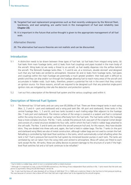
The Nimrod Review Introduction 18.1
- Page 463 and 464:
The Nimrod Review 462 The three yea
- Page 465 and 466:
The Nimrod Review 18.19 18.20 18.21
- Page 467 and 468:
The Nimrod Review 466 ‘Bow Tie’
- Page 469 and 470:
The Nimrod Review The ‘organisati
- Page 471 and 472:
The Nimrod Review 18.38 470 1 Accid
- Page 473 and 474:
The Nimrod Review Current position
- Page 475 and 476:
The Nimrod Review (6) There is a bi
- Page 477 and 478:
The Nimrod Review 476 by the IPT an
- Page 479 and 480:
The Nimrod Review 478 trails’ rat
- Page 481 and 482:
The Nimrod Review 480 Meeting / Wor
- Page 483 and 484:
The Nimrod Review 482 operational t
- Page 485 and 486:
The Nimrod Review 484 19.34.16 ”A
- Page 487 and 488:
The Nimrod Review 486
- Page 489 and 490:
The Nimrod Review Four Key Principl
- Page 491 and 492:
The Nimrod Review 20.12 20.13 490 1
- Page 493 and 494:
The Nimrod Review 20.24 20.25 492 S
- Page 495 and 496:
The Nimrod Review 494 (8) Mandatory
- Page 497 and 498:
The Nimrod Review 496 I. Clarificat
- Page 499 and 500:
The Nimrod Review 498 issues person
- Page 501 and 502:
The Nimrod Review 500 Recommendatio
- Page 503 and 504:
The Nimrod Review 502 Head of the M
- Page 505 and 506:
The Nimrod Review 504 Defence Airs
- Page 507 and 508:
The Nimrod Review 506 those who are
- Page 509 and 510:
The Nimrod Review 21.37 Paragraph 6
- Page 511 and 512:
MAA The Nimrod Review Head of the M
- Page 513 and 514:
The Nimrod Review 512 will also mai
- Page 515 and 516:
The Nimrod Review 21.59 21.60 Objec
- Page 517 and 518:
The Nimrod Review 21.71 21.72 21.73
- Page 519 and 520:
The Nimrod Review 21.80 21.81 Objec
- Page 521 and 522:
The Nimrod Review 520 Recommendatio
- Page 523 and 524:
The Nimrod Review Recommendations E
- Page 525 and 526:
The Nimrod Review 21.110 524 The BO
- Page 527 and 528:
The Nimrod Review 21.119 526 in a p
- Page 529 and 530:
The Nimrod Review 21.129 21.130 Obj
- Page 531 and 532:
The Nimrod Review 530 provide overs
- Page 533 and 534:
The Nimrod Review 21.152 532 nd I w
- Page 535 and 536:
The Nimrod Review Introduction 22.1
- Page 537 and 538:
The Nimrod Review 22.12 Third, Safe
- Page 539 and 540:
The Nimrod Review 538 22.16.1 First
- Page 541 and 542:
The Nimrod Review Genesis of Safety
- Page 543 and 544:
The Nimrod Review 22.27 22.28 542 T
- Page 545 and 546:
The Nimrod Review Six Principles fo
- Page 547 and 548:
The Nimrod Review 546 (2) Common se
- Page 549 and 550:
The Nimrod Review 548
- Page 551 and 552:
The Nimrod Review Introduction 23.1
- Page 553 and 554:
The Nimrod Review Life Extension Pr
- Page 555 and 556:
The Nimrod Review 554 not represent
- Page 557 and 558:
The Nimrod Review 23.35 556 I consu
- Page 559 and 560:
The Nimrod Review Lesson Learned -
- Page 561 and 562:
The Nimrod Review Introduction 24.1
- Page 563 and 564:
The Nimrod Review 24.12 562 nor per
- Page 565 and 566:
The Nimrod Review Introduction 25.1
- Page 567 and 568:
The Nimrod Review Conclusions 25.16
- Page 569 and 570:
The Nimrod Review Introduction 26.1
- Page 571 and 572:
The Nimrod Review Introduction 27.1
- Page 573 and 574:
The Nimrod Review Professor Reason
- Page 575 and 576:
The Nimrod Review Safety Managers 2
- Page 577 and 578:
The Nimrod Review The critical role
- Page 579 and 580:
The Nimrod Review 578
- Page 581 and 582:
The Nimrod Review 29.6 XV230 29.7 5
- Page 583 and 584:
The Nimrod Review FI Fatigue Index
- Page 585 and 586:
The Nimrod Review 584
- Page 587:
ACKNOWLEDGEMENTS Acknowledgements A