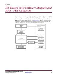
- Page 1 and 2:
Virtex-6 Libraries Guide forHDL Des
- Page 3 and 4:
Table of ContentsXilinx Trademarks
- Page 5 and 6:
Available Attributes ..............
- Page 7 and 8:
Port Descriptions..................
- Page 9 and 10:
For More Information...............
- Page 11 and 12:
ODDR...............................
- Page 13 and 14:
Design Entry Method ...............
- Page 15 and 16:
Chapter 1About this GuideThis HDL g
- Page 17 and 18:
Chapter 2About UnimacrosThis sectio
- Page 19 and 20:
Chapter 2: About UnimacrosName Dire
- Page 21 and 22:
Chapter 2: About UnimacrosVHDL Inst
- Page 23 and 24:
Chapter 2: About UnimacrosINIT_76 =
- Page 25 and 26:
Chapter 2: About Unimacros.INIT_50(
- Page 27 and 28:
Chapter 2: About UnimacrosBRAM_SING
- Page 29 and 30:
Chapter 2: About UnimacrosWRITE_WID
- Page 31 and 32:
Chapter 2: About UnimacrosBRAM_SIZE
- Page 33 and 34:
Chapter 2: About UnimacrosINITP_02
- Page 35 and 36:
Chapter 2: About Unimacros.INIT_61(
- Page 37 and 38:
Chapter 2: About UnimacrosName Dire
- Page 39 and 40:
Chapter 2: About UnimacrosDesign En
- Page 41 and 42:
Chapter 2: About UnimacrosINIT_1E =
- Page 43 and 44:
Chapter 2: About Unimacros// Xilinx
- Page 45 and 46:
Chapter 2: About Unimacros.INIT_7B(
- Page 47 and 48:
Chapter 2: About UnimacrosName Dire
- Page 49 and 50:
Chapter 2: About UnimacrosVerilog I
- Page 51 and 52:
Chapter 2: About UnimacrosName Dire
- Page 53 and 54:
Chapter 2: About UnimacrosVerilog I
- Page 55 and 56:
Chapter 2: About UnimacrosDesign En
- Page 57 and 58:
Chapter 2: About UnimacrosADDSUB_MA
- Page 59 and 60:
Chapter 2: About UnimacrosVerilog I
- Page 61 and 62:
Chapter 2: About UnimacrosInstantia
- Page 63 and 64:
Chapter 2: About UnimacrosCOUNTER_T
- Page 65 and 66:
Chapter 2: About UnimacrosFor More
- Page 67 and 68:
Chapter 2: About UnimacrosInstantia
- Page 69 and 70:
Chapter 2: About UnimacrosMACC_MACR
- Page 71 and 72:
Chapter 2: About Unimacros);LOAD =>
- Page 73 and 74:
Chapter 2: About UnimacrosAvailable
- Page 75 and 76:
Chapter 3Functional CategoriesThis
- Page 77 and 78:
Chapter 3: Functional CategoriesCon
- Page 79 and 80:
Chapter 3: Functional CategoriesSli
- Page 81 and 82:
Chapter 4About Design ElementsThis
- Page 83 and 84:
Chapter 4: About Design ElementsBSC
- Page 85 and 86:
Chapter 4: About Design ElementsVHD
- Page 87 and 88:
Chapter 4: About Design ElementsVer
- Page 89 and 90:
Chapter 4: About Design ElementsVer
- Page 91 and 92:
Chapter 4: About Design ElementsVer
- Page 93 and 94:
Chapter 4: About Design ElementsAva
- Page 95 and 96:
Chapter 4: About Design ElementsAva
- Page 97 and 98:
Chapter 4: About Design ElementsVer
- Page 99 and 100:
Chapter 4: About Design ElementsVer
- Page 101 and 102:
Chapter 4: About Design ElementsBUF
- Page 103 and 104:
Chapter 4: About Design ElementsVer
- Page 105 and 106:
Chapter 4: About Design ElementsVer
- Page 107 and 108:
Chapter 4: About Design ElementsVer
- Page 109 and 110:
Chapter 4: About Design ElementsVHD
- Page 111 and 112:
Chapter 4: About Design ElementsVHD
- Page 113 and 114:
Chapter 4: About Design ElementsVHD
- Page 115 and 116:
Chapter 4: About Design ElementsDes
- Page 117 and 118: Chapter 4: About Design ElementsDCI
- Page 119 and 120: Chapter 4: About Design ElementsDNA
- Page 121 and 122: Chapter 4: About Design ElementsDSP
- Page 123 and 124: Chapter 4: About Design ElementsPor
- Page 125 and 126: Chapter 4: About Design ElementsAtt
- Page 127 and 128: Chapter 4: About Design Elements);-
- Page 129 and 130: Chapter 4: About Design Elements);.
- Page 131 and 132: Chapter 4: About Design ElementsVer
- Page 133 and 134: Chapter 4: About Design ElementsVHD
- Page 135 and 136: Chapter 4: About Design ElementsFDR
- Page 137 and 138: Chapter 4: About Design ElementsFIF
- Page 139 and 140: Chapter 4: About Design ElementsAtt
- Page 141 and 142: Chapter 4: About Design ElementsFIF
- Page 143 and 144: Chapter 4: About Design ElementsAtt
- Page 145 and 146: Chapter 4: About Design ElementsFRA
- Page 147 and 148: Chapter 4: About Design ElementsVer
- Page 149 and 150: Chapter 4: About Design ElementsInt
- Page 151 and 152: Chapter 4: About Design ElementsDes
- Page 153 and 154: Chapter 4: About Design ElementsVHD
- Page 155 and 156: Chapter 4: About Design ElementsVHD
- Page 157 and 158: Chapter 4: About Design ElementsIBU
- Page 159 and 160: Chapter 4: About Design ElementsVer
- Page 161 and 162: Chapter 4: About Design ElementsAva
- Page 163 and 164: Chapter 4: About Design ElementsVHD
- Page 165 and 166: Chapter 4: About Design ElementsDes
- Page 167: Chapter 4: About Design ElementsIDD
- Page 171 and 172: Chapter 4: About Design ElementsAva
- Page 173 and 174: Chapter 4: About Design ElementsIOB
- Page 175 and 176: Chapter 4: About Design ElementsIOD
- Page 177 and 178: Chapter 4: About Design ElementsAtt
- Page 179 and 180: Chapter 4: About Design ElementsISE
- Page 181 and 182: Chapter 4: About Design ElementsAtt
- Page 183 and 184: Chapter 4: About Design ElementsVer
- Page 185 and 186: Chapter 4: About Design ElementsKEE
- Page 187 and 188: Chapter 4: About Design ElementsLDC
- Page 189 and 190: Chapter 4: About Design ElementsLUT
- Page 191 and 192: Chapter 4: About Design ElementsPor
- Page 193 and 194: Chapter 4: About Design ElementsLUT
- Page 195 and 196: Chapter 4: About Design ElementsPor
- Page 197 and 198: Chapter 4: About Design ElementsLUT
- Page 199 and 200: Chapter 4: About Design ElementsPor
- Page 201 and 202: Chapter 4: About Design ElementsLUT
- Page 203 and 204: Chapter 4: About Design ElementsInp
- Page 205 and 206: Chapter 4: About Design ElementsLUT
- Page 207 and 208: Chapter 4: About Design ElementsInp
- Page 209 and 210: Chapter 4: About Design ElementsLUT
- Page 211 and 212: Chapter 4: About Design ElementsInp
- Page 213 and 214: Chapter 4: About Design ElementsLUT
- Page 215 and 216: Chapter 4: About Design ElementsInp
- Page 217 and 218: Chapter 4: About Design ElementsMMC
- Page 219 and 220:
Chapter 4: About Design ElementsDes
- Page 221 and 222:
Chapter 4: About Design ElementsCLK
- Page 223 and 224:
Chapter 4: About Design Elements.DI
- Page 225 and 226:
Chapter 4: About Design ElementsPor
- Page 227 and 228:
Chapter 4: About Design ElementsCLK
- Page 229 and 230:
Chapter 4: About Design ElementsMUX
- Page 231 and 232:
Chapter 4: About Design ElementsMUX
- Page 233 and 234:
Chapter 4: About Design ElementsMUX
- Page 235 and 236:
Chapter 4: About Design ElementsMUX
- Page 237 and 238:
Chapter 4: About Design ElementsMUX
- Page 239 and 240:
Chapter 4: About Design ElementsMUX
- Page 241 and 242:
Chapter 4: About Design ElementsOBU
- Page 243 and 244:
Chapter 4: About Design ElementsOBU
- Page 245 and 246:
Chapter 4: About Design ElementsOBU
- Page 247 and 248:
Chapter 4: About Design ElementsODD
- Page 249 and 250:
Chapter 4: About Design ElementsOR2
- Page 251 and 252:
Chapter 4: About Design ElementsPor
- Page 253 and 254:
Chapter 4: About Design ElementsDDR
- Page 255 and 256:
Chapter 4: About Design ElementsPCI
- Page 257 and 258:
Chapter 4: About Design ElementsPUL
- Page 259 and 260:
Chapter 4: About Design ElementsPUL
- Page 261 and 262:
Chapter 4: About Design ElementsRAM
- Page 263 and 264:
Chapter 4: About Design ElementsRAM
- Page 265 and 266:
Chapter 4: About Design ElementsRAM
- Page 267 and 268:
Chapter 4: About Design ElementsAva
- Page 269 and 270:
Chapter 4: About Design ElementsRAM
- Page 271 and 272:
Chapter 4: About Design ElementsRAM
- Page 273 and 274:
Chapter 4: About Design ElementsFor
- Page 275 and 276:
Chapter 4: About Design ElementsRAM
- Page 277 and 278:
Chapter 4: About Design ElementsVer
- Page 279 and 280:
Chapter 4: About Design ElementsVHD
- Page 281 and 282:
Chapter 4: About Design ElementsPor
- Page 283 and 284:
Chapter 4: About Design ElementsAtt
- Page 285 and 286:
Chapter 4: About Design ElementsINI
- Page 287 and 288:
Chapter 4: About Design Elements.IN
- Page 289 and 290:
Chapter 4: About Design ElementsRAM
- Page 291 and 292:
Chapter 4: About Design ElementsPor
- Page 293 and 294:
Chapter 4: About Design ElementsAtt
- Page 295 and 296:
Chapter 4: About Design ElementsINI
- Page 297 and 298:
Chapter 4: About Design ElementsRST
- Page 299 and 300:
Chapter 4: About Design Elements.IN
- Page 301 and 302:
Chapter 4: About Design Elements);.
- Page 303 and 304:
Chapter 4: About Design ElementsPor
- Page 305 and 306:
Chapter 4: About Design ElementsSRL
- Page 307 and 308:
Chapter 4: About Design ElementsVer
- Page 309 and 310:
Chapter 4: About Design ElementsPor
- Page 311 and 312:
Chapter 4: About Design ElementsVer
- Page 313 and 314:
Chapter 4: About Design ElementsPor
- Page 315 and 316:
Chapter 4: About Design ElementsVHD
- Page 317 and 318:
Chapter 4: About Design ElementsTEM
- Page 319 and 320:
Chapter 4: About Design ElementsUSR


