Xilinx Virtex-6 Libraries Guide for HDL Designs
Xilinx Virtex-6 Libraries Guide for HDL Designs
Xilinx Virtex-6 Libraries Guide for HDL Designs

Create successful ePaper yourself
Turn your PDF publications into a flip-book with our unique Google optimized e-Paper software.
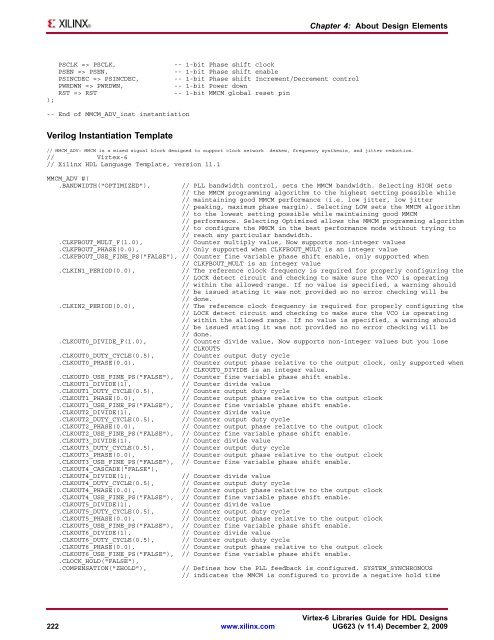
Chapter 4: About Design Elements);PSCLK => PSCLK,PSEN => PSEN,PSINCDEC => PSINCDEC,PWRDWN => PWRDWN,RST => RST-- 1-bit Phase shift clock-- 1-bit Phase shift enable-- 1-bit Phase shift Increment/Decrement control-- 1-bit Power down-- 1-bit MMCM global reset pin-- End of MMCM_ADV_inst instantiationVerilog Instantiation Template// MMCM_ADV: MMCM is a mixed signal block designed to support clock network deskew, frequency synthesis, and jitter reduction.// <strong>Virtex</strong>-6// <strong>Xilinx</strong> <strong>HDL</strong> Language Template, version 11.1MMCM_ADV #(.BANDWIDTH("OPTIMIZED"),// PLL bandwidth control, sets the MMCM bandwidth. Selecting HIGH sets// the MMCM programming algorithm to the highest setting possible while// maintaining good MMCM per<strong>for</strong>mance (i.e. low jitter, low jitter// peaking, maximum phase margin). Selecting LOW sets the MMCM algorithm// to the lowest setting possible while maintaining good MMCM// per<strong>for</strong>mance. Selecting Optimized allows the MMCM programming algorithm// to configure the MMCM in the best per<strong>for</strong>mance mode without trying to// reach any particular bandwidth.// Counter multiply value, Now supports non-integer values// Only supported when CLKFBOUT_MULT is an integer value.CLKFBOUT_MULT_F(1.0),.CLKFBOUT_PHASE(0.0),.CLKFBOUT_USE_FINE_PS("FALSE"), // Counter fine variable phase shift enable, only supported when// CLKFBOUT_MULT is an integer value.CLKIN1_PERIOD(0.0),// The reference clock frequency is required <strong>for</strong> properly configuring the// LOCK detect circuit and checking to make sure the VCO is operating// within the allowed range. If no value is specified, a warning should// be issued stating it was not provided so no error checking will be// done..CLKIN2_PERIOD(0.0),.CLKOUT0_DIVIDE_F(1.0),.CLKOUT0_DUTY_CYCLE(0.5),.CLKOUT0_PHASE(0.0),.CLKOUT0_USE_FINE_PS("FALSE"),.CLKOUT1_DIVIDE(1),.CLKOUT1_DUTY_CYCLE(0.5),.CLKOUT1_PHASE(0.0),.CLKOUT1_USE_FINE_PS("FALSE"),.CLKOUT2_DIVIDE(1),.CLKOUT2_DUTY_CYCLE(0.5),.CLKOUT2_PHASE(0.0),.CLKOUT2_USE_FINE_PS("FALSE"),.CLKOUT3_DIVIDE(1),.CLKOUT3_DUTY_CYCLE(0.5),.CLKOUT3_PHASE(0.0),.CLKOUT3_USE_FINE_PS("FALSE"),.CLKOUT4_CASCADE("FALSE"),.CLKOUT4_DIVIDE(1),.CLKOUT4_DUTY_CYCLE(0.5),.CLKOUT4_PHASE(0.0),.CLKOUT4_USE_FINE_PS("FALSE"),.CLKOUT5_DIVIDE(1),.CLKOUT5_DUTY_CYCLE(0.5),.CLKOUT5_PHASE(0.0),.CLKOUT5_USE_FINE_PS("FALSE"),.CLKOUT6_DIVIDE(1),.CLKOUT6_DUTY_CYCLE(0.5),.CLKOUT6_PHASE(0.0),.CLKOUT6_USE_FINE_PS("FALSE"),.CLOCK_HOLD("FALSE"),.COMPENSATION("ZHOLD"),// The reference clock frequency is required <strong>for</strong> properly configuring the// LOCK detect circuit and checking to make sure the VCO is operating// within the allowed range. If no value is specified, a warning should// be issued stating it was not provided so no error checking will be// done.// Counter divide value, Now supports non-integer values but you lose// CLKOUT5// Counter output duty cycle// Counter output phase relative to the output clock, only supported when// CLKOUT0_DIVIDE is an integer value.// Counter fine variable phase shift enable.// Counter divide value// Counter output duty cycle// Counter output phase relative to the output clock// Counter fine variable phase shift enable.// Counter divide value// Counter output duty cycle// Counter output phase relative to the output clock// Counter fine variable phase shift enable.// Counter divide value// Counter output duty cycle// Counter output phase relative to the output clock// Counter fine variable phase shift enable.// Counter divide value// Counter output duty cycle// Counter output phase relative to the output clock// Counter fine variable phase shift enable.// Counter divide value// Counter output duty cycle// Counter output phase relative to the output clock// Counter fine variable phase shift enable.// Counter divide value// Counter output duty cycle// Counter output phase relative to the output clock// Counter fine variable phase shift enable.// Defines how the PLL feedback is configured. SYSTEM_SYNCHRONOUS// indicates the MMCM is configured to provide a negative hold time<strong>Virtex</strong>-6 <strong>Libraries</strong> <strong>Guide</strong> <strong>for</strong> <strong>HDL</strong> <strong>Designs</strong>222 www.xilinx.com UG623 (v 11.4) December 2, 2009