- Page 1 and 2:
Motores diesel POWERTECH ® de 10.5
- Page 3 and 4:
Concesionarios John Deere Las modif
- Page 5 and 6:
Motores POWERTECH ® 6105HF y 6125H
- Page 7 and 8:
Motores POWERTECH ® 6105HRW y 6125
- Page 9 and 10:
POWERTECH ® 6105ADW Vista lateral
- Page 11 and 12:
Motores diesel POWERTECH ® 6125 Ti
- Page 13 and 14:
SECCIÓN 01—Información general
- Page 15 and 16:
Página Grupo 000—Seguridad .....
- Page 17 and 18:
Manejo seguro de los fluidos—Evit
- Page 19 and 20:
Seguridad ATENCION: El ácido sulf
- Page 21 and 22:
Dar servicio en forma segura Recoge
- Page 23 and 24:
Iluminar adecuadamente la zona de t
- Page 25 and 26:
Vertido adecuado de desechos Seguri
- Page 27 and 28:
Designación de modelo del motor Ej
- Page 29 and 30:
Etiqueta de códigos de opción del
- Page 31 and 32:
Combustible diesel Para obtener inf
- Page 33 and 34:
Lubricidad de combustible diesel El
- Page 35 and 36:
Aceite para motores diesel—Motore
- Page 37 and 38:
Intervalos de cambio de aceite prol
- Page 39 and 40:
Grasa Escoger el tipo de grasa a us
- Page 41 and 42:
Aditivos de refrigerante La concent
- Page 43 and 44:
IMPORTANTE: SIEMPRE mantener el niv
- Page 45 and 46:
IMPORTANTE: NUNCA llenar el sistema
- Page 47 and 48:
Sección 02 Reparación y ajustes
- Page 49 and 50:
Índice Página Página Inspección
- Page 51 and 52:
Grupo 010 Guía de reconstrucción,
- Page 53 and 54:
Desconexión delalínea de entrada
- Page 55 and 56:
Guía de reconstrucción, rodaje y
- Page 57 and 58:
4. Montar el motor al adaptador tra
- Page 59 and 60:
Guía de reconstrucción, rodaje y
- Page 61 and 62:
Guía de reconstrucción, rodaje y
- Page 63 and 64:
Guía de reconstrucción, rodaje y
- Page 65 and 66:
Guía de reconstrucción, rodaje y
- Page 67 and 68:
Revisar el nivel de aceite más fre
- Page 69 and 70:
Revisión y mantenimiento del siste
- Page 71 and 72:
Revisión del sistema eléctrico Gu
- Page 73 and 74:
Recomendaciones generales para el a
- Page 75 and 76:
Retiro e instalación de cubierta d
- Page 77 and 78:
Sustitución de empaquetadura de cu
- Page 79 and 80:
Culata y válvulas IMPORTANTE: NO i
- Page 81 and 82:
Culata y válvulas 8. Ajustar la pr
- Page 83 and 84:
Culata y válvulas Valor especifica
- Page 85 and 86:
Culata y válvulas ATENCION: Un seg
- Page 87 and 88:
Sistemas de combustible controlados
- Page 89 and 90:
NOTA: La culata puede quitarse sin
- Page 91 and 92:
Diagnóstico de fallas en empaqueta
- Page 93 and 94:
Culata y válvulas Secuencia de ins
- Page 95 and 96:
Desarmado e inspección del conjunt
- Page 97 and 98:
Armado de conjunto de balancines y
- Page 99 and 100:
Inspección y medición deválvulas
- Page 101 and 102:
Limpieza, inspección y medición d
- Page 103 and 104:
Limpieza e inspección de culata IM
- Page 105 and 106:
Medición del espesor de la culata
- Page 107 and 108:
Medición del D.I. de la guía dev
- Page 109 and 110:
Rectificación de los asientos de l
- Page 111 and 112:
Medición de cavidades de asientos
- Page 113 and 114:
Culata y válvulas IMPORTANTE: Los
- Page 115 and 116:
Instalación del manguito del inyec
- Page 117 and 118:
NOTA: Inspeccionar minuciosamente l
- Page 119 and 120:
Culata y válvulas Sustitución de
- Page 121 and 122:
6. Taponar las cavidades de vaciado
- Page 123 and 124:
13. Aplicar una cantidad abundante
- Page 125 and 126:
Instalación de manguito del inyect
- Page 127 and 128:
9. Enroscar la tuerca impulsora JDG
- Page 129 and 130:
Limpieza e inspección de la parte
- Page 131 and 132:
Instalación de la culata Culata y
- Page 133 and 134:
Apriete por vueltas de pernos de la
- Page 135 and 136:
IMPORTANTE: Los motores de 12.5 lit
- Page 137 and 138:
IMPORTANTE: Los procedimientos de a
- Page 139 and 140:
Culata y válvulas 4. Ajustar el es
- Page 141 and 142:
Culata y válvulas Valor especifica
- Page 143 and 144:
Grupo 030 Bloque de cilindros, cami
- Page 145 and 146: Instalación de la placa delantera
- Page 147 and 148: Bloque de cilindros, camisas, pisto
- Page 149 and 150: Retiro de los pistones y bielas Blo
- Page 151 and 152: NOTA: Siempre seguir las indicacion
- Page 153 and 154: Medición de proyección de camisas
- Page 155 and 156: 4. Quitar la guarnición cuadrada (
- Page 157 and 158: 6. Quitar la guarnición cuadrada (
- Page 159 and 160: 2. Examinar el DI de la camisa visu
- Page 161 and 162: Códigos de fecha de fabricación d
- Page 163 and 164: 3. Quitar los aros (B) del pistón
- Page 165 and 166: Revisión de desgaste de ranuras pa
- Page 167 and 168: Inspección de pasador de pistón y
- Page 169 and 170: IMPORTANTE: SIEMPRE medir las camis
- Page 171 and 172: Inspección y medición de cojinete
- Page 173 and 174: Inspección de biela y tapa Bloque
- Page 175 and 176: 7. Usar un micrómetro interior par
- Page 177 and 178: Bloque de cilindros, camisas, pisto
- Page 179 and 180: Instalación del buje del pasador d
- Page 181 and 182: Bloque de cilindros, camisas, pisto
- Page 183 and 184: Medición del bloque de cilindros C
- Page 185 and 186: Comprobación de proyección de cam
- Page 187 and 188: Instalación de camisas de cilindro
- Page 189 and 190: Armado de pistones y bielas NOTA: L
- Page 191 and 192: 1. Escalonar la posición de las se
- Page 193 and 194: 9. Sumergir los pernos y arandelas
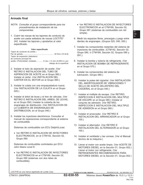
- Page 195: Revisión de rotación del motor pa
- Page 199 and 200: Secuencia de apriete del amortiguad
- Page 201 and 202: Revisión del juego axial del cigü
- Page 203 and 204: 4. Enroscar la tuerca hexagonal gra
- Page 205 and 206: Revisión de descentramiento de sup
- Page 207 and 208: Inspección y reparación del volan
- Page 209 and 210: Retiro e instalación de la caja de
- Page 211 and 212: 3. Separar el sello de su caja usan
- Page 213 and 214: Análisis de fallas de cigüeñal y
- Page 215 and 216: 8. Fijar un martillo deslizante D01
- Page 217 and 218: Retiro del cigüeñal 1. Quitar la
- Page 219 and 220: Cigüeñal, cojinetes de bancada y
- Page 221 and 222: Cigüeñal, cojinetes de bancada y
- Page 223 and 224: 8. Después de terminar la rectific
- Page 225 and 226: Inspección de cojinetes de empuje
- Page 227 and 228: Instalación de los insertos de los
- Page 229 and 230: 7. Apretar los pernos del cojinete
- Page 231 and 232: Instalación de sello de aceite tra
- Page 233 and 234: Cigüeñal, cojinetes de bancada y
- Page 235 and 236: Cigüeñal, cojinetes de bancada y
- Page 237 and 238: Cigüeñal, cojinetes de bancada y
- Page 239 and 240: 4. Instalar el instalador de sellos
- Page 241 and 242: Cigüeñal, cojinetes de bancada y
- Page 243 and 244: Secuencia de apriete de cubierta de
- Page 245 and 246: Arbol de levas y engranajes de dist
- Page 247 and 248:
Ajuste del juego entre dientes de e
- Page 249 and 250:
5. Sacar los seis pernos retenedore
- Page 251 and 252:
Arbol de levas y engranajes de dist
- Page 253 and 254:
Retiro e instalación del árbol de
- Page 255 and 256:
8. Quitar la bomba de suministro de
- Page 257 and 258:
Instalación del árbol de levas de
- Page 259 and 260:
7. Instalar el acoplador impulsor (
- Page 261 and 262:
11. Girar el árbol de levas en sus
- Page 263 and 264:
Inspección visual del árbol de le
- Page 265 and 266:
Inspección delóbulo de sensor de
- Page 267 and 268:
Arbol de levas y engranajes de dist
- Page 269 and 270:
10. Quitar el conjunto de herramien
- Page 271 and 272:
Arbol de levas y engranajes de dist
- Page 273 and 274:
Arbol de levas y engranajes de dist
- Page 275 and 276:
Conjunto de filtro y caja del acond
- Page 277 and 278:
Retiro, inspección e instalación
- Page 279 and 280:
Sistema de lubricación Retiro, ins
- Page 281 and 282:
4. Quitar las dos tuercas hexagonal
- Page 283 and 284:
Sistema de lubricación 4. Instalar
- Page 285 and 286:
5. Quitar la empaquetadura (B) de l
- Page 287 and 288:
4. Segundo: Empezando con el primer
- Page 289 and 290:
Retiro e instalación del tubo de a
- Page 291 and 292:
Sistema de lubricación NOTA: Ubica
- Page 293 and 294:
Sustitución de cojinetes en conjun
- Page 295 and 296:
Sistema de enfriamiento Despiece de
- Page 297 and 298:
Sistema de enfriamiento Valor espec
- Page 299 and 300:
Sustitución de tensor de correas U
- Page 301 and 302:
Limpieza e inspección de los compo
- Page 303 and 304:
Retiro de termostatos Sistema de en
- Page 305 and 306:
Prueba de temperatura de apertura d
- Page 307 and 308:
Retiro e instalación del calefacto
- Page 309 and 310:
Prolongación de vida útil del tur
- Page 311 and 312:
Retiro del turboalimentador Sistema
- Page 313 and 314:
DEFECTOS DE SALIDA DE LA ENVUELTA D
- Page 315 and 316:
Sistema de admisión de aire y esca
- Page 317 and 318:
2. Inspeccionar las paletas del rot
- Page 319 and 320:
Prueba de turboalimentador en banco
- Page 321 and 322:
Prueba de juego radial de cojinete
- Page 323 and 324:
Prelubricación del turboalimentado
- Page 325 and 326:
Conectar la línea de entrada de ac
- Page 327 and 328:
Sistema de admisión de aire y esca
- Page 329 and 330:
Retiro, inspección e instalación
- Page 331 and 332:
Retiro e instalación de conjunto d
- Page 333 and 334:
Sistema de combustible NOTA: Los pr
- Page 335 and 336:
Retiro e instalación de alternador
- Page 337 and 338:
Sección 03 Teoría de funcionamien
- Page 339 and 340:
Funcionamiento general del motor Gr
- Page 341 and 342:
El eje de balancines de inyectores
- Page 343 and 344:
Funcionamiento del motor básico A
- Page 345 and 346:
Funcionamiento del motor básico CT
- Page 347 and 348:
Funcionamiento del motor básico A
- Page 349 and 350:
Funcionamiento del motor básico Fo
- Page 351 and 352:
Funcionamiento del turboalimentador
- Page 353 and 354:
Página Grupo 150—Diagnóstico y
- Page 355 and 356:
Acerca de esta sección del manual
- Page 357 and 358:
2 Revisión de presión excesiva en
- Page 359 and 360:
Diagnóstico y pruebas observables
- Page 361 and 362:
Diagnóstico y pruebas observables
- Page 363 and 364:
Prueba con dinamómetro 1. Conectar
- Page 365 and 366:
Revisión de la presión de aceite
- Page 367 and 368:
3. Si parece que el aumento de pres
- Page 369 and 370:
Prueba de presión del sistema de e
- Page 371 and 372:
Diagnóstico y pruebas observables
- Page 373 and 374:
Diagnóstico y pruebas observables
- Page 375 and 376:
Revisión de fugas en sistema de ad
- Page 377 and 378:
Comprobación de la sincronización
- Page 379 and 380:
Revisión de profundidad del sensor
- Page 381 and 382:
Sección 05 Herramientas y otros ma
- Page 383 and 384:
Guía de reconstrucción, rodaje y
- Page 385 and 386:
Herramientas de reparación y otros
- Page 387 and 388:
Herramientas de reparación y otros
- Page 389 and 390:
Herramientas de reparación y otros
- Page 391 and 392:
Herramientas esenciales para bloque
- Page 393 and 394:
Herramientas de reparación y otros
- Page 395 and 396:
Herramientas de reparación y otros
- Page 397 and 398:
Otros materiales para bloque de cil
- Page 399 and 400:
Herramientas de reparación y otros
- Page 401 and 402:
Herramientas de reparación y otros
- Page 403 and 404:
Herramientas esenciales para el ár
- Page 405 and 406:
Herramientas de reparación y otros
- Page 407 and 408:
Herramientas esenciales para el sis
- Page 409 and 410:
Herramientas esenciales para el sis
- Page 411 and 412:
Herramientas esenciales para los si
- Page 413 and 414:
Herramientas esenciales para diagn
- Page 415 and 416:
Grupo 190 Herramientas de servicio
- Page 417 and 418:
Página Grupo 200—Especificacione
- Page 419 and 420:
Grupo 200 Especificaciones de repar
- Page 421 and 422:
Valores de apriete de tornillería
- Page 423 and 424:
Especificaciones de reparación y g
- Page 425 and 426:
Especificaciones de reparación y g
- Page 427 and 428:
Especificaciones de bloque de cilin
- Page 429 and 430:
Especificaciones de reparación y g
- Page 431 and 432:
Especificaciones para cigüeñal, c
- Page 433 and 434:
Especificaciones de reparación y g
- Page 435 and 436:
Especificaciones de reparación y g
- Page 437 and 438:
Especificaciones de reparación y g
- Page 439 and 440:
Especificaciones de reparación y g
- Page 441 and 442:
Especificaciones de sistemas de arr
- Page 443 and 444:
Especificaciones de diagnósticos y
- Page 445 and 446:
Especificaciones para diagnóstico
- Page 447 and 448:
Especificaciones para diagnóstico
- Page 449 and 450:
Especificaciones para diagnóstico
- Page 451 and 452:
Índice alfabético Página Página
- Page 453 and 454:
Índice alfabético Página Página
- Page 455 and 456:
Índice alfabético Página Página