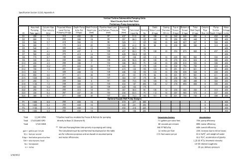
- Page 1 and 2:
BIDDING DOCUMENTS for the Ward Coun
- Page 3 and 4:
Advertisement for Bids
- Page 5 and 6:
these qualifications will be disqua
- Page 7 and 8:
00 10 00 INSTRUCTIONS TO BIDDERS 1.
- Page 9 and 10:
6. Substitutions or "equivalent" It
- Page 11 and 12:
B. In evaluating Bids, Owner / Engi
- Page 13 and 14:
Bid Proposal Form
- Page 15 and 16:
Colorado River Municipal Water Dist
- Page 17 and 18:
Bid Package Colorado River Municipa
- Page 19 and 20:
Colorado River Municipal Water Dist
- Page 21 and 22:
1. Legal / Financial Colorado River
- Page 23 and 24:
Colorado River Municipal Water Dist
- Page 25 and 26:
Colorado River Municipal Water Dist
- Page 27 and 28:
Colorado River Municipal Water Dist
- Page 29 and 30:
Colorado River Municipal Water Dist
- Page 31 and 32:
Colorado River Municipal Water Dist
- Page 33 and 34:
Colorado River Municipal Water Dist
- Page 35 and 36:
Colorado River Municipal Water Dist
- Page 37 and 38:
Colorado River Municipal Water Dist
- Page 42 and 43:
Performance Bond (sample)
- Page 44 and 45:
Payment Bond (sample)
- Page 46 and 47:
Certificate of Insurance (sample)
- Page 48 and 49:
Standard General Conditions
- Page 50 and 51:
Copyright ©1996 National Society o
- Page 52 and 53:
6.07 Patent Fees and Royalties ....
- Page 54 and 55:
GENERAL CONDITIONS ARTICLE 1 - DEFI
- Page 56 and 57:
Act of 1954 (42 USC Section 2011 et
- Page 58 and 59:
A. CONTRACTOR’s Review of Contrac
- Page 60 and 61:
from retaining copies of the Contra
- Page 62 and 63:
CONTRACTOR shall be responsible for
- Page 64 and 65:
maintain. OWNER shall deliver to CO
- Page 66 and 67:
directors, partners, employees, age
- Page 68 and 69:
y words reading that no like, equiv
- Page 70 and 71:
perils or causes of loss covered by
- Page 72 and 73:
maintaining and supervising of safe
- Page 74 and 75:
1. IS ATTRIBUTABLE TO BODILY INJURY
- Page 76 and 77:
ARTICLE 9 - ENGINEER’S STATUS DUR
- Page 78 and 79:
that should be allowed as a result
- Page 80 and 81:
TRACTOR is liable, imposed by Laws
- Page 82 and 83:
c. where one or more tiers of subco
- Page 84 and 85:
equipment, or fails to perform the
- Page 86 and 87:
a. the Work has progressed to the p
- Page 88 and 89:
certification of Substantial Comple
- Page 90 and 91:
labor, materials, or equipment as r
- Page 92 and 93:
Supplementary Conditions (Revised b
- Page 94 and 95:
G. Add a new paragraph 1.01 A. 53:
- Page 96 and 97:
A. Delete Paragraph 2.05 A. of the
- Page 98 and 99:
3. Make copies of reference standar
- Page 100 and 101:
obligations of Bidder under these b
- Page 102 and 103:
underground coverage where applicab
- Page 104 and 105:
7. be maintained in effect until fi
- Page 106 and 107:
B. Add a new paragraph immediately
- Page 108 and 109:
(b) a new certificate of coverage s
- Page 110 and 111:
SC‐6.18 G. In the event that Bidd
- Page 112 and 113:
uncovered for observation, or requi
- Page 114 and 115:
3. Shall not undertake any of the r
- Page 116 and 117:
unable to agree as to the effect of
- Page 118 and 119:
A. Add the following to paragraph 1
- Page 120 and 121:
01 11 00 SUMMARY OF WORK 1.00 GENER
- Page 122 and 123:
shall install the SCADA equipment a
- Page 124 and 125:
Payment Procedures
- Page 126 and 127:
) Provide amounts for items that do
- Page 128 and 129:
3. On the basis of these agreements
- Page 130 and 131:
01 31 00 PROJECT MANAGEMENT AND COO
- Page 132 and 133:
E. Coordinate with architectural re
- Page 134 and 135:
Restore structures which may have b
- Page 136 and 137:
D. Assume full responsibility for t
- Page 138 and 139:
B. Conduct all construction activit
- Page 140 and 141:
C. Owner, CMAR or Engineer may use
- Page 142 and 143:
Project Coordination
- Page 144 and 145:
a. Preliminary construction schedul
- Page 146 and 147:
1.08 REQUESTS FOR MODIFICATIONS A.
- Page 148 and 149:
2) Horizontal and vertical location
- Page 150 and 151:
01 32 16 CONSTRUCTION PROGRESS SCHE
- Page 152 and 153:
1.05 FLOAT TIME A. Define float tim
- Page 154 and 155:
Submittal Procedures
- Page 156 and 157:
adequate time for the submittal rev
- Page 158 and 159:
2. Define abbreviations and symbols
- Page 160 and 161:
c. Dimensions or other data that do
- Page 162 and 163:
C. Include the amount if cost savin
- Page 164 and 165:
1.11 RESUBMISSION REQUIREMENTS A. M
- Page 166 and 167:
01 40 00 QUALITY REQUIRMENTS 1.00 G
- Page 168 and 169:
5. Do not affect the continuing rig
- Page 170 and 171:
B. Payment for non‐conforming Wor
- Page 172 and 173:
2. Changes are made in applicable q
- Page 174 and 175:
c. Provide corporation cocks at lea
- Page 176 and 177:
24 1360 100 13.676 (L) 27 1530 88 1
- Page 178 and 179:
Complete appropriate test report ne
- Page 180 and 181:
h. Energize switchgear. Measure and
- Page 182 and 183:
4.03 TOLERANCES A. Monitor fabricat
- Page 184 and 185:
I. Agency Reports: After each test,
- Page 186 and 187:
01 50 00 TEMPORARY FACILITIES AND C
- Page 188 and 189:
D. Work outside the hours or 7:00 a
- Page 190 and 191:
01 57 00 TEMPORARY CONTROLS 1.00 GE
- Page 192 and 193:
B. Use forms required by the Texas
- Page 194 and 195:
C. Remove temporary control when no
- Page 196 and 197:
01 60 00 PRODUCT REQUIREMENTS 1.00
- Page 198 and 199:
C. Two or more items of the same ki
- Page 200 and 201:
A. Provide suitable anchor bolts fo
- Page 202 and 203:
01 70 00 EXECUTION AND CLOSEOUT REQ
- Page 204 and 205:
1.07 FINAL APPLICATION FOR PAYMENT
- Page 206 and 207:
Final Cleaning
- Page 208 and 209:
D. Clean wall surfaces to remove di
- Page 210 and 211:
01 75 00 STARTING AND ADJUSTING 1.0
- Page 212 and 213:
D. Unless specifically stated other
- Page 214 and 215:
3.06 INITIAL MAINTENANCE A. Maintai
- Page 216 and 217:
01 78 23 OPERATION AND MAINTENANCE
- Page 218 and 219:
B. Include only the information tha
- Page 220:
Appendix A Contract Documents for R
- Page 223 and 224:
Raw Water Supply Well Sites Ward Co
- Page 225 and 226:
Division 03
- Page 227 and 228:
Colorado River Municipal Water Dist
- Page 229 and 230:
Colorado River Municipal Water Dist
- Page 231 and 232:
Colorado River Municipal Water Dist
- Page 233 and 234:
Colorado River Municipal Water Dist
- Page 235 and 236:
Colorado River Municipal Water Dist
- Page 237 and 238:
Colorado River Municipal Water Dist
- Page 239 and 240:
Colorado River Municipal Water Dist
- Page 241 and 242:
Division 05
- Page 243 and 244:
Colorado River Municipal Water Dist
- Page 245 and 246:
Colorado River Municipal Water Dist
- Page 247 and 248:
Division 11
- Page 249 and 250:
Colorado River Municipal Water Dist
- Page 251 and 252:
Colorado River Municipal Water Dist
- Page 253 and 254:
Colorado River Municipal Water Dist
- Page 255 and 256:
Specification Section 11 97 00, Att
- Page 257 and 258:
S:\Projects\CRMWD\WR11.0143_CRMWD_W
- Page 259 and 260:
Division 22
- Page 261 and 262:
Colorado River Municipal Water Dist
- Page 263 and 264:
Colorado River Municipal Water Dist
- Page 265 and 266:
Colorado River Municipal Water Dist
- Page 267 and 268:
Colorado River Municipal Water Dist
- Page 269 and 270:
Colorado River Municipal Water Dist
- Page 271 and 272:
Colorado River Municipal Water Dist
- Page 273 and 274:
Colorado River Municipal Water Dist
- Page 275 and 276:
Colorado River Municipal Water Dist
- Page 277 and 278:
Colorado River Municipal Water Dist
- Page 279 and 280:
Division 26
- Page 281 and 282:
Colorado River Municipal Water Dist
- Page 283 and 284:
PROJECT: OWNER: CONTRACTOR: ENGINEE
- Page 285 and 286:
PROJECT: OWNER: CONTRACTOR: ENGINEE
- Page 287 and 288:
PROJECT: OWNER: CONTRACTOR: ENGINEE
- Page 289 and 290:
PROJECT: OWNER: CONTRACTOR: ENGINEE
- Page 291 and 292:
Colorado River Municipal Water Dist
- Page 293 and 294:
Colorado River Municipal Water Dist
- Page 295 and 296:
Colorado River Municipal Water Dist
- Page 297 and 298:
Colorado River Municipal Water Dist
- Page 299 and 300:
Colorado River Municipal Water Dist
- Page 301 and 302:
Colorado River Municipal Water Dist
- Page 303 and 304:
Colorado River Municipal Water Dist
- Page 305 and 306:
Colorado River Municipal Water Dist
- Page 307 and 308:
Colorado River Municipal Water Dist
- Page 309 and 310:
Colorado River Municipal Water Dist
- Page 311 and 312:
Colorado River Municipal Water Dist
- Page 313 and 314:
Colorado River Municipal Water Dist
- Page 315 and 316:
Colorado River Municipal Water Dist
- Page 317 and 318:
Colorado River Municipal Water Dist
- Page 319 and 320:
Colorado River Municipal Water Dist
- Page 321 and 322:
Colorado River Municipal Water Dist
- Page 323 and 324:
Colorado River Municipal Water Dist
- Page 325 and 326:
Colorado River Municipal Water Dist
- Page 327 and 328:
Colorado River Municipal Water Dist
- Page 329 and 330:
Colorado River Municipal Water Dist
- Page 331 and 332:
Colorado River Municipal Water Dist
- Page 333 and 334:
Colorado River Municipal Water Dist
- Page 335 and 336:
Colorado River Municipal Water Dist
- Page 337 and 338:
Colorado River Municipal Water Dist
- Page 339 and 340:
Colorado River Municipal Water Dist
- Page 341 and 342:
Colorado River Municipal Water Dist
- Page 343 and 344:
Colorado River Municipal Water Dist
- Page 345 and 346:
Colorado River Municipal Water Dist
- Page 347 and 348:
Colorado River Municipal Water Dist
- Page 349 and 350:
Colorado River Municipal Water Dist
- Page 351 and 352:
Colorado River Municipal Water Dist
- Page 353 and 354:
Colorado River Municipal Water Dist
- Page 355 and 356:
Colorado River Municipal Water Dist
- Page 357 and 358:
Colorado River Municipal Water Dist
- Page 359 and 360:
Colorado River Municipal Water Dist
- Page 361 and 362:
Colorado River Municipal Water Dist
- Page 363 and 364:
Colorado River Municipal Water Dist
- Page 365 and 366:
Colorado River Municipal Water Dist
- Page 367 and 368:
Colorado River Municipal Water Dist
- Page 369 and 370:
Division 31
- Page 371 and 372:
Colorado River Municipal Water Dist
- Page 373 and 374:
Colorado River Municipal Water Dist
- Page 375 and 376:
Colorado River Municipal Water Dist
- Page 377 and 378:
Colorado River Municipal Water Dist
- Page 379 and 380:
Colorado River Municipal Water Dist
- Page 381 and 382:
Colorado River Municipal Water Dist
- Page 383 and 384:
Division 32
- Page 385 and 386:
Colorado River Municipal Water Dist
- Page 387 and 388:
Colorado River Municipal Water Dist
- Page 389 and 390:
Division 40
- Page 391 and 392:
Colorado River Municipal Water Dist
- Page 393 and 394:
Colorado River Municipal Water Dist
- Page 395 and 396:
Colorado River Municipal Water Dist
- Page 397 and 398:
Colorado River Municipal Water Dist
- Page 399 and 400:
Colorado River Municipal Water Dist
- Page 401 and 402:
Colorado River Municipal Water Dist
- Page 403 and 404:
Colorado River Municipal Water Dist
- Page 405 and 406:
Colorado River Municipal Water Dist
- Page 407 and 408:
Colorado River Municipal Water Dist
- Page 409 and 410:
Colorado River Municipal Water Dist
- Page 411 and 412:
Appendix A
- Page 413 and 414:
Electric Service Guidelines July 20
- Page 415 and 416:
ELECTRIC SERVICE GUIDELINES These E
- Page 417 and 418:
FOREWORD Page 4 SECTION 100 GENERAL
- Page 419 and 420:
FOREWORD This booklet is issued by
- Page 421 and 422:
SECTION 100 - GENERAL INFORMATION 1
- Page 423 and 424:
100.01.22 Service Agreement Any com
- Page 425 and 426:
100.02.03 Inspection and Approval o
- Page 427 and 428:
100.05.02 Standard Secondary Voltag
- Page 429 and 430:
SECTION 200 - CLEARANCES 200.01 Tex
- Page 431 and 432:
CLEARANCE OF SWIMMING POOLS FROM OV
- Page 433 and 434:
CLEARANCES OF PADMOUNTED TRANSFORME
- Page 435 and 436:
SECTION 300 - OVERHEAD SERVICE 300.
- Page 437 and 438:
TYPICAL PERMANENT SERVICE DROP FIGU
- Page 439 and 440:
MAXIMUM SERVICE DROP LENGTH FOR RES
- Page 441 and 442:
NOTES: OVERHEAD SERVICE TO A PERMAN
- Page 443 and 444:
OVERHEAD SERVICE TO TWO OR THREE ME
- Page 445 and 446:
OVERHEAD THREE WIRE DELTA SERVICES
- Page 447 and 448:
400.03 Underground Services to Seco
- Page 449 and 450:
UNDERGROUND SERVICE SELF CONTAINED
- Page 451 and 452:
UNDERGROUND SERVICE ONE SECONDARY S
- Page 453 and 454:
UNDERGROUND SERVICE, TWO OR MORE SE
- Page 455 and 456:
SECTION 500 - METERING AND ASSOCIAT
- Page 457 and 458:
500.06.03 Meterpacks Meterpacks for
- Page 459 and 460:
500.08 Service Enclosures (Distribu
- Page 461 and 462:
COMPANY - CUSTOMER RESPONSIBILITY (
- Page 463 and 464:
47 APPLICATION WIRES PHASE VOLTS 3
- Page 465 and 466:
49 APPLICATION WIRES PHASE VOLTS ME
- Page 467 and 468:
TRANSOCKET CONFIGURATIONS AND CONNE
- Page 469 and 470:
TRANSOCKET CONFIGURATIONS AND CONNE
- Page 471 and 472:
TYPICAL SERVICE ENCLOSURES (CONTINU
- Page 473 and 474:
METER SOCKET CONNECTIONS AND VOLTAG
- Page 475 and 476:
METER SOCKET CONNECTIONS AND VOLTAG
- Page 477 and 478:
METER SOCKET CONNECTIONS AND VOLTAG
- Page 479 and 480:
TEMPORARY SERVICE POLE FROM OVERHEA
- Page 481 and 482:
TWO HOLE COMPRESSION LUGS FOR TERMI
- Page 483 and 484:
TWO HOLE COMPRESSION LUGS FOR TERMI
- Page 485 and 486:
ONE HOLE COMPRESSION LUGS FOR SUBME
- Page 487 and 488:
Information to be Supplied by Elect
- Page 489 and 490:
DO YOU KNOW THE LAW? Texas Law & OS
- Page 491 and 492:
Appendix B
- Page 493 and 494:
40 90 00 INSTRUMENTATION AND CONTRO
- Page 495 and 496:
1.03 GUARANTEE 12. Underwriters' La
- Page 497 and 498:
4. Electrical and interconnection d
- Page 499 and 500:
B. Use test equipment and instrumen
- Page 501 and 502:
1 40 90 02 SUPERVISORY CONTROL AND
- Page 503 and 504:
C. System Components: The system wi
- Page 505 and 506:
. ICS 1.1, Safety Guidelines for th
- Page 507 and 508:
C. Post-submittal Sample Screens fo
- Page 509 and 510:
1.03 QUALITY ASSURANCE A. Suppliers
- Page 511 and 512:
1.06 WARRANTY 5. Two (2) spare PLC
- Page 513 and 514:
J. Utilize a power turn-on time del
- Page 515 and 516:
6) High CPU temperature 7) Scan tim
- Page 517 and 518:
4. Analog I/O Modules: a. Input mod
- Page 519 and 520:
2.06 SURGE SUPPRESSOR A. Surge supp
- Page 521 and 522:
7. Wiring shall be run enclosed in
- Page 523 and 524:
2.10 UNINTERRUPTIBLE POWER SUPPLY (
- Page 525 and 526:
2.14 GIGABIT ETHERNET 3-PORT SWITCH
- Page 527 and 528:
3.04 TESTS A. All elements of the S
- Page 529 and 530:
a) For analog devices: Required and
- Page 531 and 532:
3. Evening meetings to review the d
- Page 533 and 534:
3.08 FUNCTIONAL DEMONSTRATION TEST
- Page 535 and 536:
3.10 TRAINING A. Provide an integra
- Page 537 and 538:
Colorado River Municipal Water Dist
- Page 540:
This page intentionally left blank.
- Page 559 and 560:
Appendix B Project Manual for Verti
- Page 561 and 562:
This page intentionally left blank.
- Page 563 and 564:
This page intentionally left blank.
- Page 565 and 566:
This page intentionally left blank.
- Page 567 and 568:
Copyright © 2010: National Society
- Page 569 and 570:
AGREEMENT THIS AGREEMENT is by and
- Page 571 and 572:
ARTICLE 7 - PAYMENT PROCEDURES 7.01
- Page 573 and 574:
1. This Agreement (pages 00520-1 to
- Page 575 and 576:
1) Engineer will review Seller’s
- Page 578 and 579:
RESOLUTION VERTICLE TURBINE SUBMERS
- Page 581:
This page intentionally left blank.
- Page 585:
This page intentionally left blank.
- Page 599:
CONFLICT OF INTEREST QUESTIONNAIRE
- Page 602 and 603:
Service Information: The areas wher
- Page 605:
This page intentionally left blank.
- Page 619 and 620: Copyright © 2010: National Society
- Page 621 and 622: ARTICLE 8 - BUYER’S RIGHTS.......
- Page 623 and 624: 10. Claim—A demand or assertion b
- Page 625 and 626: 1.02 Terminology 35. Supplementary
- Page 627 and 628: B. The progress schedule will be ac
- Page 629 and 630: 3.04 Amending and Clarifying Contra
- Page 631 and 632: B. All Goods, and all equipment and
- Page 633 and 634: C. Submittal Procedures: 1. Before
- Page 635 and 636: 3. use of the Goods by Buyer; 4. an
- Page 637 and 638: for the Goods. Seller shall also re
- Page 639 and 640: tests of the Goods at Seller’s fa
- Page 641 and 642: D. Buyer’s Acceptance of Non-Conf
- Page 643 and 644: C. If Engineer does not render a fo
- Page 645 and 646: 10.04 Suspension of or Reduction in
- Page 647 and 648: 11.04 Breach and Termination A. Buy
- Page 649 and 650: 12.03 Buyer’s Infringement A. Buy
- Page 651 and 652: of the firm or to an officer of the
- Page 653 and 654: of an offense directly or indirectl
- Page 655 and 656: e. Excess or Umbrella Liability 1)
- Page 657 and 658: separately identified item of Unit
- Page 659 and 660: F. The award will be consistent wit
- Page 661: BID ADDENDUM FAILURE TO RETURN THIS
- Page 666 and 667: Daniel B. Stephens & Associates, In
- Page 668 and 669: Daniel B. Stephens & Associates, In
- Page 670 and 671: Technical Specifications
- Page 673 and 674: This page intentionally left blank.
- Page 675 and 676: Colorado River Municipal Water Dist
- Page 677 and 678: SECTION 01019 CONTRACT CONSIDERATIO
- Page 679 and 680: This page intentionally left blank.
- Page 681 and 682: This page intentionally left blank.
- Page 683 and 684: This page intentionally left blank.
- Page 685 and 686: Colorado River Municipal Water Dist
- Page 687 and 688: Colorado River Municipal Water Dist
- Page 689 and 690: Colorado River Municipal Water Dist
- Page 691 and 692: Colorado River Municipal Water Dist
- Page 693 and 694: This page intentionally left blank.
- Page 695 and 696: This page intentionally left blank.
- Page 697 and 698: This page intentionally left blank.
- Page 699 and 700: Colorado River Municipal Water Dist
- Page 701 and 702: Colorado River Municipal Water Dist
- Page 703 and 704: Colorado River Municipal Water Dist
- Page 705 and 706: Colorado River Municipal Water Dist
- Page 707 and 708: Colorado River Municipal Water Dist
- Page 709 and 710: Colorado River Municipal Water Dist
- Page 711 and 712: This page intentionally left blank.
- Page 713 and 714:
This page intentionally left blank.


