

Bravo & Brava • 1995 To 2000
Bravo & Brava • 1995 To 2000
Bravo & Brava • 1995 To 2000

Create successful ePaper yourself
Turn your PDF publications into a flip-book with our unique Google optimized e-Paper software.
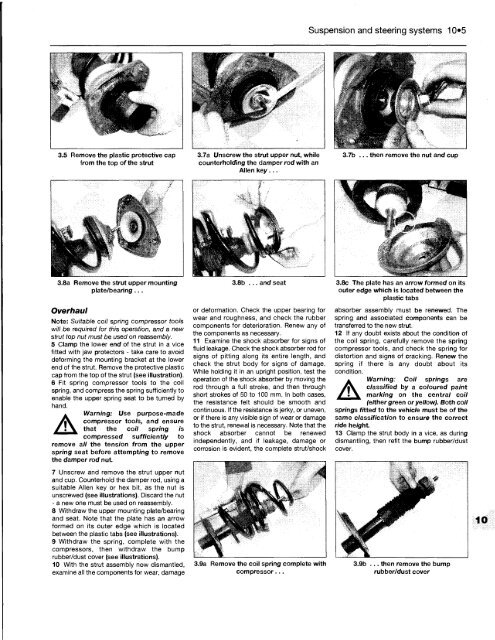
3.5 Remove the plastic protective cap<br />
from the top of the strut<br />
3.8a Remove the strut upper mounting<br />
plate/bearing ...<br />
Overhaul<br />
Note: Suitable coil spring compressor tools<br />
will be required for this operation, and a new<br />
strut top nut must be used on reassembly.<br />
5 Clamp the lower end of the strut in a vice<br />
fitted with jaw protectors - take care to avoid<br />
deforming the mounting bracket at the lower<br />
end of the strut. Remove the protective plastic<br />
cap from the top of the strut (see illustration).<br />
6 Fit spring compressor tools to the coil<br />
spring, and compress the spring sufficiently to<br />
enable the upper spring seat to be turned by<br />
hand.<br />
A<br />
Warning: Use purpose-made<br />
compressor tools, and ensure<br />
that the coil spring is<br />
compressed sufficiently to<br />
remove all the tension from the upper<br />
spring seat before attempting to remove<br />
the damper rod nut.<br />
7 Unscrew and remove the strut upper nut<br />
and cup. Counterhold the damper rod, using a<br />
suitable Allen key or hex bit, as the nut is<br />
unscrewed (see illustrations). Discard the nut<br />
- a new one must be used on reassembly.<br />
8 Withdraw the upper mounting plate/bearing<br />
and seat. Note that the plate has an arrow<br />
formed on its outer edge which is located<br />
between the plastic tabs (see illustrations).<br />
9 Withdraw the spring, complete with the<br />
compressors, then withdraw the bump<br />
rubber/dust cover (see illustrations).<br />
10 With the strut assembly now dismantled,<br />
examine all the components for wear, damage<br />
3.7a Unscrew the strut upper nut, while<br />
counterholding the damper rod with an<br />
Allen key ...<br />
3.8b ... and seat<br />
or deformation. Check the upper bearing for<br />
wear and roughness, and check the rubber<br />
components for deterioration. Renew any of<br />
the components as necessary.<br />
11 Examine the shock absorber for signs of<br />
fluid leakage. Check the shock absorber rod for<br />
signs of pitting along its entire length, and<br />
check the strut body for signs of damage.<br />
While holding it in an upright position, test the<br />
operation of the shock absorber by moving the<br />
rod through a full stroke, and then through<br />
short strokes of 50 to 100 mm. In both cases,<br />
the resistance felt should be smooth and<br />
continuous. If the resistance is jerky, or uneven,<br />
or if there is any visible sign of wear or damage<br />
to the strut, renewal is necessary. Note that the<br />
shock absorber cannot be renewed<br />
independently, and if leakage, damage or<br />
corrosion is evident, the complete strut/shock<br />
3.9a Remove the coil spring complete with<br />
compressor...<br />
Suspension and steering systems 10*5<br />
3.7b ... then remove the nut and cup<br />
3.8c The plate has an arrow formed on its<br />
outer edge which is located between the<br />
plastic tabs<br />
absorber assembly must be renewed. The<br />
spring and associated components can be<br />
transferred to the new strut.<br />
12 If any doubt exists about the condition of<br />
the coil spring, carefully remove the spring<br />
compressor tools, and check the spring for<br />
distortion and signs of cracking. Renew the<br />
spring if there is any doubt about its<br />
condition.<br />
A<br />
Warning: Coil springs are<br />
classified by a coloured paint<br />
marking on the central coil<br />
(either green or yellow). Both coil<br />
springs fitted to the vehicle must be of the<br />
same classification to ensure the correct<br />
ride height.<br />
13 Clamp the strut body in a vice, as during<br />
dismantling, then refit the bump rubber/dust<br />
cover.<br />
3.9b ... then remove the bump<br />
rubber/dust cover


