

Bravo & Brava • 1995 To 2000
Bravo & Brava • 1995 To 2000
Bravo & Brava • 1995 To 2000

Create successful ePaper yourself
Turn your PDF publications into a flip-book with our unique Google optimized e-Paper software.
2E»14 Engine removal and overhaul procedures<br />
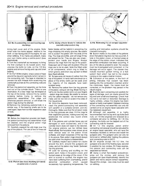
5.5 No 3 connecting rod and bearing cap<br />
markings<br />
timing belt cover end of the engine. Note<br />
which side the marks appear, relative to the<br />
front- or rear-facing side of the engine, for use<br />
when refitting. If no marks are present, make<br />
your own marks using a centre-punch (see<br />
illustration).<br />
6 Turn the crankshaft as necessary to bring<br />
the first- crankpin to its lowest point, then<br />
unscrew the bolts (or nuts, on the 1.6 litre<br />
engine) and remove the big-end cap and shell<br />
bearing.<br />
7 On the 1.6 litre engine, wrap a piece of tape<br />
around the big-end cap bolts (which remain in<br />
the connecting rod). The tape is intended to<br />
prevent the bolt threads from scratching the<br />
crankshaft journals as the connecting rods are<br />
removed.<br />
8 Push the piston/rod assembly up the bore<br />
and out of the cylinder block. There is one<br />
reservation; if a wear ridge has developed at<br />
the top of the bores, remove this by careful<br />
scraping before trying to remove the<br />
piston/rod assemblies. The ridge will<br />
otherwise prevent removal, or will break the<br />
piston rings during the attempt.<br />
9 Remove the remaining pistons/rods in a<br />
similar way. If the bearing shells are to be<br />
used again, tape them to their respective caps<br />
or rods.<br />
Inspection<br />
10 Before the inspection process can begin,<br />
the piston/connecting rod assemblies must<br />
be cleaned, and the original piston rings<br />
removed from the pistons.<br />
11 Carefully expand the old rings over the<br />
top of the pistons. The use of two or three old<br />
It''**<br />
5.15 Piston size class marking (arrowed)<br />
on underside of piston<br />
5.11a Using a feeler blade to remove the<br />
second compression ring<br />
feeler blades will be helpful in preventing the<br />
rings dropping into empty grooves. Be careful<br />
not to scratch the piston with the ends of the<br />
ring. The rings are brittle, and will snap if they<br />
are spread too far. They are also very sharp -<br />
protect your hands and fingers. Always<br />
remove the rings from the top of the piston.<br />
Keep each set of rings with its piston if the old<br />
rings are to be re-used. Note the fitted order<br />
of all components, which ring is fitted to<br />
which groove, and which way up each is fitted<br />
(see illustrations).<br />
12 Scrape away all traces of carbon from the<br />
top of the piston. A hand-held wire brush (or a<br />
piece of fine emery cloth) can be used, once<br />
the majority of the deposits have been<br />
scraped away.<br />
13 Remove the carbon from the ring grooves<br />
in the piston, using an old ring. Break the ring in<br />
half to do this (be careful not to cut your fingers<br />
- piston rings are sharp). Be careful to remove<br />
only the carbon deposits - do not remove any<br />
metal, and do not nick or scratch the sides of<br />
the ring grooves.<br />
14 Once the deposits have been removed,<br />
clean the piston/connecting rod assembly<br />
with paraffin or a suitable solvent, and dry<br />
thoroughly. Make sure that the oil return holes<br />
in the ring grooves are clear. Fit the rings to<br />
their respective grooves, making sure they are<br />
positioned the correct way round where<br />
applicable.<br />
15 If the pistons and cylinder bores are not<br />
damaged or worn excessively,, and if the<br />
cylinder block does not need to be rebored,<br />
the original pistons can be refitted (see<br />
illustration). Normal piston wear shows up as<br />
even vertical wear on the piston thrust<br />
surfaces, and slight looseness of the top ring<br />
in its groove. New piston rings should always<br />
be used when the engine is reassembled.<br />
16 Carefully inspect each piston for cracks<br />
around the skirt, around the gudgeon pin<br />
holes, and at the piston ring 'lands' (between<br />
the ring grooves).<br />
17 Look for scoring and scuffing on the<br />
piston skirt, holes in the piston crown, and<br />
burned areas at the edge of the crown. If the<br />
skirt is scored or scuffed, the engine may<br />
have been suffering from overheating, and/or<br />
abnormal combustion which caused<br />
excessively high operating temperatures. The<br />
5.11 b Removing the oil scraper expander<br />
ring<br />
cooling and lubrication systems should be<br />
checked thoroughly.<br />
18 Scorch marks on the sides of the pistons<br />
show that piston ring blow-by has occurred. A<br />
hole in the piston crown, or burned areas at<br />
the edge of the piston crown, indicates that<br />
abnormal combustion has been occurring. If<br />
any of the above problems exist, the causes<br />
must be investigated and corrected, or the<br />
damage will occur again. The causes may<br />
include incorrect ignition timing, or a fuel<br />
system fault which has led to the engine<br />
running on too weak a fuel/air mixture.<br />
19 Corrosion of the piston, in the form of<br />
pitting, indicates that coolant has been<br />
leaking into the combustion chamber and/or<br />
the crankcase. Again, the cause must be<br />
corrected, or the problem may persist in the<br />
rebuilt engine.<br />
20 Examine each connecting rod carefully for<br />
signs of damage, such as cracks around the<br />
big-end and small-end bearings. Check that<br />
the rod is not bent or distorted. Damage is<br />
highly unlikely, unless the engine has been<br />
seized or badly overheated. Detailed checking<br />
of the connecting rod assembly can only be<br />
carried out by an engine repair specialist with<br />
the necessary equipment.<br />
21 Although not essential, it is highly<br />
recommended that the big-end cap bolts (and<br />
nuts, on 1.6 litre engines) are renewed as a<br />
complete set prior to refitting. On 1.6 litre<br />
engines, the bolts can be tapped out of the<br />
connecting rods for renewal.<br />
22 On 1.2 litre engines, piston and/or<br />
connecting rod renewal should be entrusted to<br />
an engine repair specialist, who will have the<br />
necessary facilities to remove and install the<br />
gudgeon pins. The gudgeon pins can only be<br />
removed or refitted after heating the pistons<br />
and connecting rods to 240°C.<br />
23 On engines except the 1.2 litre, the<br />
gudgeon pins are of the floating type, secured<br />
in position by two circlips. On these engines,<br />
the pistons and connecting rods can be<br />
separated as follows.<br />
24 Using a small flat-bladed screwdriver,<br />
prise out the circlips, and remove the<br />
gudgeon pin (see illustrations). Identify the<br />
piston and rod to ensure correct reassembly.<br />
Discard the circlips - new ones must be used<br />
on refitting.


