

Bravo & Brava • 1995 To 2000
Bravo & Brava • 1995 To 2000
Bravo & Brava • 1995 To 2000

Create successful ePaper yourself
Turn your PDF publications into a flip-book with our unique Google optimized e-Paper software.
5B»6 Ignition system<br />
4.14 Removing the engine top cover<br />
identical readings - compare with the<br />
specified value.<br />
10 <strong>To</strong> check the secondary resistances, the<br />
HT leads must be disconnected from the<br />
coil HT terminals. Ensure that the cylinder<br />
number markings are visible, so that the<br />
leads can be correctly refitted.<br />
11 Check the secondary resistance between<br />
the HT terminals for cylinders 1 and 4, then<br />
between those for cylinders 2 and 3. Again,<br />
both tests should give near-identical readings.<br />
12 If the test results are not as expected,<br />
bear in mind that a fault is normally only<br />
indicated .by a zero or infinity reading. Do not<br />
condemn the coil without consulting a FIAT<br />
dealer or automotive electrician first.<br />
Refitting<br />
13 Refitting is a reversal of removal, making<br />
sure that the LT and HT wiring is correctly and<br />
securely reconnected.<br />
1.8 litre models<br />
Removal<br />
14 Unscrew the oil filler cap, and remove the<br />
two bolts concealed underneath. Remove the<br />
six main cover bolts, and lift off the engine top<br />
cover, for access to the ignition coil<br />
assemblies (see illustration).<br />
15 Disconnect the wiring plugs from the<br />
ignition coil which fits over each spark plug<br />
(see illustration).<br />
16 If all four coils are to be removed, mark<br />
the coil assemblies for position, noting that<br />
No 1 coil is nearest the timing belt end of the<br />
engine.<br />
4.18 Pull the coil upwards off its spark<br />
plug<br />
4.15 Disconnect the coil wiring plug<br />
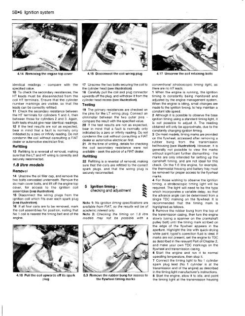
17 Unscrew the two bolts securing the coil to<br />
the cylinder head (see illustration).<br />
18 Carefully pull the coil and plug connector<br />
upwards off the plug, and withdraw it from the<br />
cylinder head recess (see illustration).<br />
Testing<br />
19 The primary resistances are checked on<br />
the pins for the LT wiring plug. Connect an<br />
ohmmeter between the two outer pins -<br />
compare the result with the specified value.<br />
20 If the test results are not as expected,<br />
bear in mind that a fault is normally only<br />
indicated by a zero or infinity reading. Do not<br />
condemn the coil without consulting a FIAT<br />
dealer or automotive electrician first.<br />
21 At the time of writing, details for checking<br />
the coil secondary resistance were not<br />
available - seek the advice of a FIAT dealer.<br />
Refitting<br />
22 Refitting is a reversal of removal, making<br />
sure that the coils are refitted to the correct<br />
spark plugs, and that the wiring plug is<br />
securely reconnected.<br />
5 Ignition timing - gS<br />
checking and adjustment ^<br />
Note 1: No ignition timing specifications are<br />
available from FIAT, so the results will be of<br />
academic interest only.<br />
Note 2: Checking the timing on 1.8 litre<br />
models may not be possible with a<br />
5.3 Remove the rubber bung for access to<br />
the flywheel timing marks<br />
4.17 Unscrew the coil retaining bolts<br />
conventional stroboscopic timing light, as<br />
there are no HT leads.<br />
1 When the engine is running, the ignition<br />
timing is constantly being monitored and<br />
adjusted by the engine management system.<br />
When the engine is idling, small changes are<br />
made to the ignition timing, to help maintain a<br />
constant idle speed.<br />
2 Although it is possible to observe the base<br />
ignition timing using a standard timing light, it<br />
is not possible to adjust it. The reading<br />
obtained will only be approximate, due to the<br />
constantly changing ignition timing.<br />
3 On most models, timing marks are provided<br />
on the flywheel, accessed after removing a<br />
rubber bung from the transmission<br />
bellhousing (see illustration). However, it is<br />
generally not possible to view the marks<br />
without significant further dismantling - the<br />
marks are only intended for setting up the<br />
camshaft timing, and are not ideal for this<br />
check. On the 1.6 litre engine, for example,<br />
the thermostat housing and battery tray must<br />
be removed for proper access to the flywheel<br />
marks.<br />
4 For those wishing to observe the ignition<br />
timing, a stroboscopic timing light will be<br />
required. The light will need to be the type<br />
which incorporates a variable delay, so that<br />
the advance angle can be determined from a<br />
single TDC marking on the flywheel. It is<br />
recommended that the timing mark is<br />
highlighted as follows.<br />
5 Remove the rubber bung from the top of<br />
the transmission casing, then turn the engine<br />
slowly (using a spanner on the crankshaft<br />
pulley bolt) until the timing mark scribed on<br />
the edge of the flywheel appears in the<br />
aperture. Highlight the line with quick-drying<br />
white paint; typist's correction fluid is ideal. If<br />
marks are not present, set the engine to TDC<br />
as described in the relevant Part of Chapter 2,<br />
and make your own TDC markings on the<br />
flywheel and transmission casing.<br />
6 Start the engine and run it to normal<br />
operating temperature, then stop it.<br />
7 Connect the timing light to No 1 cylinder<br />
spark plug lead (No 1 cylinder is at the<br />
transmission end of the engine) as described<br />
in the timing light manufacturer's instructions.<br />
8 Start the engine, allow it to idle, and point<br />
the timing light at the transmission housing


