

Bravo & Brava • 1995 To 2000
Bravo & Brava • 1995 To 2000
Bravo & Brava • 1995 To 2000

You also want an ePaper? Increase the reach of your titles
YUMPU automatically turns print PDFs into web optimized ePapers that Google loves.
7A«6 Manual transmission<br />
3.50 Removing the flywheel cover<br />
46 Remove the right- and left-hand<br />
driveshafts as described in Chapter 8. The<br />
clips securing the inner joint gaiters to the<br />
transmission side flanges must be removed,<br />
and the driveshaft inner tripod joints<br />
withdrawn from the differential sun gears.<br />
47 Unscrew and remove the upper and lower<br />
bolts securing the transmission to the engine,<br />
but leave the side nut and bolt at this stage.<br />
48 The engine must now be supported while<br />
the transmission is being removed. FIAT<br />
recommend fitting an eyelet to the thermostat<br />
housing after unbolting the wiring support<br />
bracket from it, however an alternative method<br />
is to fit the lifting chain to the left-hand end of<br />
the exhaust manifold. If the latter method is<br />
used, first remove the engine top cover then<br />
attach a hoist to the manifold and take the<br />
weight of the engine. Do not support the<br />
engine with a trolley jack positioned under the<br />
sump because the position of the right-hand<br />
front engine mounting dictates that the centre<br />
of gravity of the engine mass is high, and it is<br />
quite likely that the engine will fall to one side<br />
damaging either the radiator or the rear<br />
bulkhead. As an additional precaution,<br />
position axle stands and a block of wood<br />
beneath the engine.<br />
49 Support the transmission on a trolley jack.<br />
50 Unbolt and remove the flywheel cover<br />
(see illustration).<br />
51 Unbolt the exhaust front downpipe from<br />
the exhaust manifold and support on an axle<br />
stand. Recover the gasket.<br />
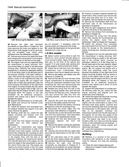
52 Working under the car, unbolt the rear<br />
engine mounting and bracket from the<br />
transmission and underbody (see<br />
illustration).<br />
53 Unbolt the front engine mounting and<br />
bracket from the front valance and<br />
transmission.<br />
54 Lower the transmission and engine<br />
slightly until the transmission is clear of the<br />
left-hand inner body panels. Unscrew and<br />
remove the remaining rear mounting nut and<br />
front mounting bolt securing the transmission<br />
to the engine, then, with the help of an<br />
assistant, withdraw the transmission directly<br />
from the left-hand end of the engine. Do not<br />
allow the weight of the transmission to rest on<br />
the clutch friction disc hub. The engine may<br />
need to be moved forward a little, but make<br />
sure that the heater hoses on the bulkhead<br />
3.52 Rear engine mounting and bracket<br />
are not strained - if necessary, drain the<br />
cooling system and disconnect the hoses.<br />
55 Lower the transmission to the ground and<br />
withdraw from under the car.<br />
1.8 litre models<br />
56 Select a solid, level surface to park the<br />
vehicle on. Give yourself enough space to<br />
move around it easily. Apply the handbrake<br />
then jack up the front of the vehicle and<br />
support it on axle stands (see Jacking and<br />
vehicle support). Remove both front wheels.<br />
57 Unbolt the air inlet duct from the engine<br />
compartment front crossmember, then<br />
disconnect it from the air cleaner and remove.<br />
58 Remove the battery and battery tray with<br />
reference to Chapter 5A.<br />
59 Remove the inlet duct from the rear of the<br />
engine compartment by disconnecting the<br />
wiring and crankcase ventilation hose, then<br />
loosening the clips and disconnecting the<br />
duct from the throttle body and air cleaner.<br />
60 Release the wiring from the rear of the<br />
battery mounting bracket, then undo the bolt<br />
and remove the relay box cover. Unscrew the<br />
nuts and remove the relay box from the<br />
mounting bracket - position the box to one<br />
side.<br />
61 Unscrew the bolts and disconnect the<br />
wiring from the battery positive terminal.<br />
62 Unbolt the remove the battery mounting<br />
bracket and unclip the remaining wiring.<br />
63 Disconnect the clutch cable from the<br />
transmission with reference to Chapter 6.<br />
64 Unscrew the nut and disconnect the earth<br />
wire from the transmission. Also disconnect<br />
the wiring from the speedometer sender.<br />
65 Unscrew the nuts and disconnect the<br />
gearchange reaction link from the<br />
transmission.<br />
66 Remove the electric cooling fan assembly<br />
from the rear of the radiator with reference to<br />
Chapter 3.<br />
67 Unscrew and remove the two upper bolts<br />
securing the transmission to the rear of the<br />
engine.<br />
68 At the right-hand side of the engine,<br />
unbolt the short engine steady bar between<br />
the cylinder head and inner body panel.<br />
69 Remove the right- and left-hand<br />
driveshafts as described in Chapter 8. If<br />
preferred, the driveshafts can remain attached<br />
to the front hub bearings, and tied to one side.<br />
70 Position a suitable container beneath the<br />
transmission, then unscrew and remove the<br />
drain plug and allow the oil to drain. On<br />
completion, refit and tighten the drain plug.<br />
71 Remove the intermediate shaft from the<br />
right-hand side of the transmission as<br />
described in Chapter 8.<br />
72 Prise the gear engagement and selector<br />
rods from the levers on the transmission.<br />
73 Remove the exhaust front downpipe as<br />
described in Chapter 4C.<br />
74 Disconnect the wiring from the starter<br />
motor, then unscrew the mounting bolts and<br />
remove the starter motor from the<br />
transmission. Refer to Chapter 5A if necessary.<br />
75 Unbolt the exhaust front downpipe<br />
securing bracket from the front of the cylinder<br />
block for access to the transmission-toengine<br />
mounting bolt. Unscrew and remove<br />
the bolt.<br />
76 The engine must now be supported while<br />
the transmission is being removed. FIAT<br />
recommend fitting an eyelet to the left-hand<br />
side of the cylinder block, however an<br />
alternative method is to fit the lifting chain to<br />
the left-hand end of the inlet manifold. Attach<br />
a suitable hoist and take the weight of the<br />
engine. Do not support the engine with a<br />
trolley jack positioned under the sump<br />
because the position of the right-hand front<br />
engine mounting dictates that the centre of<br />
gravity of the engine mass is high, and it is<br />
quite likely that the engine will fall to one side<br />
damaging either the radiator or the rear<br />
bulkhead. As an additional precaution,<br />
position axle stands and a block of wood<br />
beneath the engine.<br />
77 Support the transmission on a trolley jack.<br />
78 Working under the car, unbolt the rear<br />
engine mounting and bracket from the<br />
transmission and underbody.<br />
79 Unbolt the engine left-hand side mounting<br />
from the transmission and underbody.<br />
80 Lower the transmission and engine<br />
slightly until the transmission is clear of the<br />
left-hand inner body panels. Unscrew and<br />
remove the remaining bolts and nut securing<br />
the transmission to the engine, then, with the<br />
help of an assistant, withdraw the<br />
transmission directly from the left-hand end of<br />
the engine. Do not allow the weight of the<br />
transmission to rest on the clutch friction disc<br />
hub. The engine may need to be moved<br />
forward a little, but make sure that the heater<br />
hoses on the bulkhead are not strained - if<br />
necessary, drain the cooling system and<br />
disconnect the hoses.<br />
81 Lower the transmission to the ground and<br />
withdraw from under the car.<br />
Refitting<br />
82 Refitting is a reversal of the removal<br />
procedure with reference to the Chapters<br />
used for removal, but note the following<br />
points.<br />
a) Check the clutch release bearing with<br />
reference to Chapter 6 before refitting the<br />
transmission.


