

Bravo & Brava • 1995 To 2000
Bravo & Brava • 1995 To 2000
Bravo & Brava • 1995 To 2000

You also want an ePaper? Increase the reach of your titles
YUMPU automatically turns print PDFs into web optimized ePapers that Google loves.
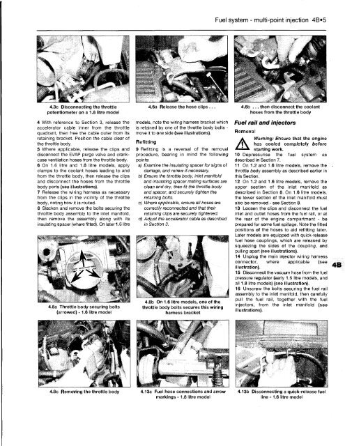
4.3c Disconnecting the throttle<br />
potentiometer on a 1.8 litre model<br />
4 With reference to Section 3, release the<br />
accelerator cable inner from the throttle<br />
quadrant, then free the cable outer from its<br />
retaining bracket. Position the cable clear of<br />
the throttle body.<br />
5 Where applicable, release the clips and<br />
disconnect the EVAP purge valve and crankcase<br />
ventilation hoses from the throttle body.<br />
6 On 1.6 litre and 1.8 litre models, apply<br />
clamps to the coolant hoses leading to and<br />
from the throttle body, then release the clips<br />
and disconnect the hoses from the throttle<br />
body ports (see illustrations).<br />
7 Release the wiring harness as necessary<br />
from the clips in the vicinity of the throttle<br />
body, noting how it is routed.<br />
8 Slacken and remove the bolts securing the<br />
throttle body assembly to the inlet manifold,<br />
then remove the assembly along with its<br />
insulating spacer (where fitted). On later 1.6 litre<br />
4.8a Throttle body securing bolts<br />
(arrowed) -1.6 litre model<br />
4.6a Release the hose clips .<br />
models, note the wiring harness bracket which<br />
is retained by one of the throttle body bolts -<br />
move it to one side (see illustrations).<br />
Refitting<br />
9 Refitting is a reversal of the removal<br />
procedure, bearing in mind the following<br />
points:<br />
a) Examine the insulating spacer for signs of<br />
damage, and renew if necessary.<br />
b) Ensure the throttle body, inlet manifold<br />
and insulating spacer mating surfaces are<br />
clean and dry, then fit the throttle body<br />
and spacer, and securely tighten the<br />
retaining bolts.<br />
c) Where applicable, ensure all hoses are<br />
correctly reconnected and that their<br />
retaining clips are securely tightened.<br />
dj Adjust the accelerator cable as described<br />
in Section 3.<br />
...__..r<br />
4.8b On 1.6 litre models, one of the<br />
throttle body bolts secures this wiring<br />
harness bracket<br />
4.8c Removing the throttle body 4.13a Fuel hose connections and arrow<br />
markings -1.8 litre model<br />
Fuel system - multi-point injection 4B»5<br />
4.6b ... then disconnect the coolant<br />
hoses from the throttle body<br />
Fuel rail and injectors<br />
Removal<br />
A<br />
Warning: Ensure that the engine<br />
has cooled completely before<br />
starting work.<br />
10 Depressurise the fuel system as<br />
described in Section 7.<br />
11 On 1.2 and 1.6 litre models, remove the<br />
throttle body assembly as described earlier in<br />
this Section.<br />
12 On 1.2 and 1.6 litre models, remove the<br />
upper section of the inlet manifold as<br />
described in Section 8. On 1.6 litre models,<br />
the lower section of the inlet manifold must<br />
also be removed - see Section 8.<br />
13 Loosen the clips and disconnect the fuel<br />
inlet and outlet hoses from the fuel rail, or at<br />
the rear of the engine compartment - be<br />
prepared for some fuel spillage. Note the fitted<br />
positions of the hoses to aid refitting later.<br />
Later models are equipped with quick-release<br />
fuel hose couplings, which are released by<br />
squeezing the sides of the coupling, and<br />
pulling apart (see illustrations).<br />
14 Unplug the main injector wiring harness<br />
connector, where applicable (see<br />
illustration).<br />
15 Disconnect the vacuum hose from the fuel<br />
pressure regulator (early 1.6 litre models, and<br />
all 1.8 litre models) (see illustration).<br />
16 Unscrew the bolts securing the fuel rail<br />
assembly to the inlet manifold, then carefully<br />
pull the fuel rail, together with the fuel<br />
injectors, from the inlet manifold (see<br />
illustrations).<br />
4.13b Disconnecting a quick-release fuel<br />
line - 1.6 litre model


