

Bravo & Brava • 1995 To 2000
Bravo & Brava • 1995 To 2000
Bravo & Brava • 1995 To 2000

You also want an ePaper? Increase the reach of your titles
YUMPU automatically turns print PDFs into web optimized ePapers that Google loves.
Refitting<br />
14 Ensure that the cylinder head and<br />
thermostat housing mating surfaces are<br />
completely clean and free from all traces of<br />
the old gasket material.<br />
15 Locate a new gasket in position on the<br />
cylinder head, then fit the thermostat housing<br />
and insert retaining bolts, tightening them<br />
securely.<br />
16 The remaining procedure is a reversal of<br />
removal, but refill the cooling system as<br />
described in Chapter 1.<br />
5 Electric cooling fan - %<strong>•</strong><br />
testing, removal and refitting<br />
Testing<br />
1 Detailed fault diagnosis should be carried<br />
out by a FIAT dealer using dedicated test<br />
equipment, but basic diagnosis can be carried<br />
out as follows. Note that on models equipped<br />
with air conditioning, two fans are fitted<br />
together with a two-speed control unit.<br />
2 If the fan does not appear to work, run the<br />
engine until normal operating temperature is<br />
reached, then allow it to idle. The fan should<br />
cut in just before the temperature gauge<br />
needle enters the red section. If not, switch off<br />
the ignition and disconnect the cooling fan<br />
motor wiring connector.<br />
3 The motor can be tested by disconnecting<br />
it from the wiring loom, and connecting a 12volt<br />
supply and an earth wire directly to it. The<br />
motor should operate - if not, the motor, or<br />
the motor wiring, is faulty.<br />
4 If the motor operates when tested as<br />
described, the fault must lie in the engine<br />
wiring harness or the temperature sensor. The<br />
temperature sensor/switch can be tested as<br />
described in Section 6. Any further fault<br />
diagnosis should be referred to a suitablyequipped<br />
FIAT dealer - do not attempt to test<br />
the electronic control unit.<br />
Removal<br />
5 Make sure that the ignition switch is turned<br />
off, and that the engine is cold.<br />
Warning: The electric fan could<br />
start to operate if the engine is A hot, even if the ignition is<br />
switched off.<br />
6 On 1.6 and 1.8 litre models, unscrew the<br />
bolts and remove the inlet air duct from over<br />
the radiator.<br />
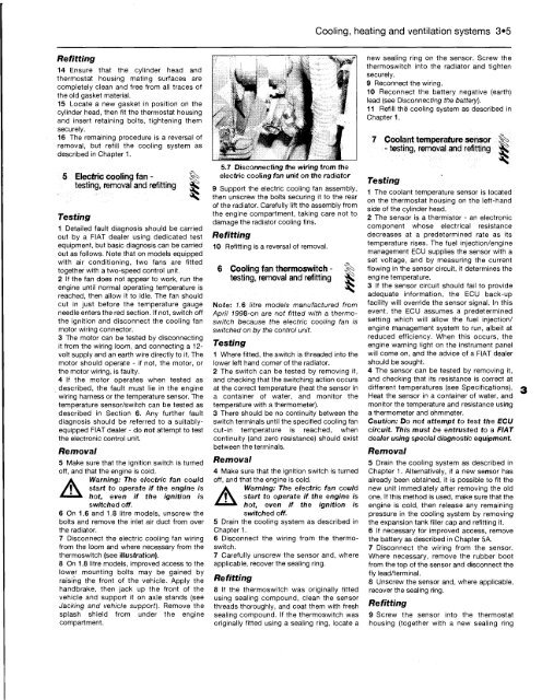
7 Disconnect the electric cooling fan wiring<br />
from the loom and where necessary from the<br />
thermoswitch (see illustration).<br />
8 On 1.8 litre models, improved access to the<br />
lower mounting bolts may be gained by<br />
raising the front of the vehicle. Apply the<br />
handbrake, then jack up the front of the<br />
vehicle and support it on axle stands (see<br />
Jacking and vehicle support). Remove the<br />
splash shield from under the engine<br />
compartment.<br />
5.7 Disconnecting the wiring from the<br />
electric cooling fan unit on the radiator<br />
9 Support the electric cooling fan assembly,<br />
then unscrew the bolts securing it to the rear<br />
of the radiator. Carefully lift the assembly from<br />
the engine compartment, taking care not to<br />
damage the radiator cooling fins.<br />
Refitting<br />
10 Refitting is a reversal of removal.<br />
6 Cooling fan thermoswitch - §|<br />
testing, removal and refitting ^<br />
Note: 7.6 litre models manufactured from<br />
April 1998-on are not fitted with a thermoswitch<br />
because the electric cooling fan is<br />
switched on by the control unit.<br />
Testing<br />
1 Where fitted, the switch is threaded into the<br />
lower left hand corner of the radiator.<br />
2 The switch can be tested by removing it,<br />
and checking that the switching action occurs<br />
at the correct temperature (heat the sensor in<br />
a container of water, and monitor the<br />
temperature with a thermometer).<br />
3 There should be no continuity between the<br />
switch terminals until the specified cooling fan<br />
cut-in temperature is reached, when<br />
continuity (and zero resistance) should exist<br />
between the terminals.<br />
Removal<br />
4 Make sure that the ignition switch is turned<br />
off, and that the engine is cold.<br />
Warning: The electric fan could<br />
start to operate if the engine is<br />
hot, even if the ignition is<br />
switched off.<br />
5 Drain the cooling system as described in<br />
Chapter 1.<br />
6 Disconnect the wiring from the thermoswitch.<br />
7 Carefully unscrew the sensor and, where<br />
applicable, recover the sealing ring.<br />
Refitting<br />
8 If the thermoswitch was originally fitted<br />
using sealing compound, clean the sensor<br />
threads thoroughly, and coat them with fresh<br />
sealing compound. If the thermoswitch was<br />
originally fitted using a sealing ring, locate a<br />
Cooling, heating and ventilation systems 3*5<br />
new sealing ring on the sensor. Screw the<br />
thermoswitch into the radiator and tighten<br />
securely.<br />
9 Reconnect the wiring.<br />
10 Reconnect the battery negative (earth)<br />
lead (see Disconnecting the battery).<br />
11 Refill the 1 cooling system as described in<br />
Chapter 1.<br />
7 Coolant temperature sensor<br />
- testing, removal and refitting Sk;<br />
Testing<br />
1 The coolant temperature sensor is located<br />
on the thermostat housing on the left-hand<br />
side of the cylinder head.<br />
2 The sensor is a thermistor - an electronic<br />
component whose electrical resistance<br />
decreases at a predetermined rate as its<br />
temperature rises. The fuel injection/engine<br />
management ECU supplies the sensor with a<br />
set voltage, and by measuring the current<br />
flowing in the sensor circuit, it determines the<br />
engine temperature.<br />
3 If the sensor circuit should fail to provide<br />
adequate information, the ECU back-up<br />
facility will override the sensor signal. In this<br />
event, the ECU assumes a predetermined<br />
setting which will allow the fuel injection/<br />
engine management system to run, albeit at<br />
reduced efficiency. When this occurs, the<br />
engine warning tight on the instrument panel<br />
will come on, and the advice of a FIAT dealer<br />
should be sought.<br />
4 The sensor can be tested by removing it,<br />
and checking that its resistance is correct at<br />
different temperatures (see Specifications).<br />
Heat the sensor in a container of water, and<br />
monitor the temperature and resistance using<br />
a thermometer and ohmmeter.<br />
Caution: Do not attempt to test the ECU<br />
circuit. This must be entrusted to a FIAT<br />
dealer using special diagnostic equipment.<br />
Removal<br />
5 Drain the cooling system as described in<br />
Chapter 1. Alternatively, if a new sensor has<br />
already been obtained, it is possible to fit the<br />
new unit immediately after removing the old<br />
one. If this method is used, make sure that the<br />
engine is cold, then release any remaining<br />
pressure in the cooling system by removing<br />
the expansion tank filler cap and refitting it.<br />
6 If necessary for improved access, remove<br />
the battery as described in Chapter 5A.<br />
7 Disconnect the wiring from the sensor.<br />
Where necessary, remove the rubber boot<br />
from the top of the sensor and disconnect the<br />
fly lead/terminal.<br />
8 Unscrew the sensor and, where applicable,<br />
recover the sealing ring.<br />
Refitting<br />
9 Screw the sensor into the thermostat<br />
housing (together with a new sealing ring


