

Bravo & Brava • 1995 To 2000
Bravo & Brava • 1995 To 2000
Bravo & Brava • 1995 To 2000

You also want an ePaper? Increase the reach of your titles
YUMPU automatically turns print PDFs into web optimized ePapers that Google loves.
2D»6 1.8 litre engine in-car repair procedures<br />
TOOL<br />
Tip<br />
The timing belt tensioning tool consists<br />
of an 8 mm bolt, two 8 mm nuts, and an<br />
oversize washer. Clamp the washer so<br />
that it is off-centre, using the two nuts<br />
VERY firmly tightened (use two smaller<br />
washers either side of the main washer,<br />
if wished). The short end of the bolt<br />
locates in the hole already shown. The<br />
off-centre washer acts like an eccentric<br />
against the tensioner rib - as the bolt is<br />
turned, the washer bears on the rib and<br />
pushes the tensioner, thus tensioning<br />
the timing belt<br />
23 Initially, the belt should be set to the<br />
maximum tension possible using reasonable<br />
force. Tighten the tensioner nut securely.<br />
24 If the camshaft sprocket bolts were<br />
loosened, tighten them to the specified<br />
torque, holding each sprocket in the same<br />
way as when they were loosened.<br />
25 Remove any locking tools used, and/or<br />
select neutral. Using a spanner or socket on<br />
the crankshaft pulley bolt, turn the engine<br />
through two complete turns in the normal<br />
direction of rotation. Check (as far as<br />
possible) that the sprocket timing marks come<br />
back into alignment.<br />
26 Loosen the tensioner nut, and align the<br />
pointer with the small hole on the tensioner<br />
backplate (see illustration). Hold the tensioner<br />
in this position, and tighten the tensioner nut to<br />
the specified torque.<br />
27 Refitting the components removed for<br />
access is a reversal of removal.<br />
I<br />
5 Timing belt sprockets<br />
and tensioner -<br />
removal and refitting<br />
Timing belt tensioner<br />
Removal<br />
1 Remove the auxiliary drivebelt as described<br />
in Chapter 1.<br />
2 Unbolt and remove the timing belt cover,<br />
which is secured by a total of eight bolts. Two<br />
of the bolts are longer than the rest - note<br />
their locations as they are removed. Recover<br />
the rubber gasket fitted between the outer<br />
and inner covers, if it is loose.<br />
Caution: Provided the timing belt is kept<br />
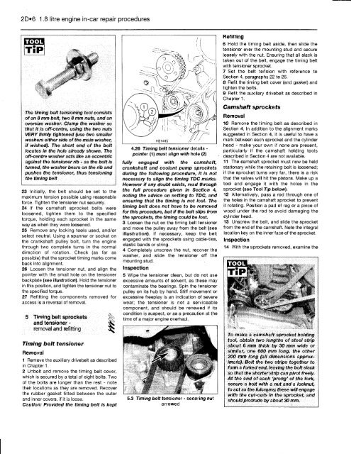
4.26 Timing belt tensioner details -<br />
pointer (1) must align with hole (2)<br />
fully engaged with the camshaft,<br />
crankshaft and coolant pump sprockets<br />
during the following procedure, it is not<br />
necessary to align the timing TDC marks.<br />
However if any doubt exists, read through<br />
the full procedure given in Section 4,<br />
noting the advice on setting to TDC, and<br />
ensuring that the timing is not lost. The<br />
timing belt does not have to be removed<br />
for this procedure, but if the belt slips from<br />
the sprockets, the timing could be lost.<br />
3 Loosen the nut on the timing belt tensioner<br />
and move the pulley away from the belt (see<br />
illustration). If necessary, keep the belt<br />
engaged with the sprockets using cable-ties,<br />
elastic bands or string.<br />
4 Completely unscrew the nut, recover the<br />
washer, and slide the tensioner off the<br />
mounting stud.<br />
Inspection<br />
5 Wipe the tensioner clean, but do not use<br />
excessive amounts of solvent, as these may<br />
contaminate the bearings. Spin the tensioner<br />
pulley on its hub by hand. Stiff movement or<br />
excessive freeplay is an indication of severe<br />
wear; the tensioner is not a serviceable<br />
component, and should be renewed if its<br />
condition is suspect, or as a precaution at the<br />
time of a major engine overhaul.<br />
5.3 Timing belt tensioner - securing nut<br />
arrowed<br />
Refitting<br />
6 Hold the timing belt aside, then slide the<br />
tensioner over the mounting stud and secure<br />
loosely with the nut. Ensuring that all slack is<br />
taken out of the belt, engage the timing belt<br />
with tensioner sprocket.<br />
7 Set the belt tension with reference to<br />
Section 4, paragraphs 22 to 26.<br />
8 Refit the timing belt cover (and gasket) and<br />
tighten the bolts.<br />
9 Refit the auxiliary drivebelt as described in<br />
Chapter 1.<br />
Camshaft sprockets<br />
Removal<br />
10 Remove the timing belt as described in<br />
Section 4. In addition to the alignment marks<br />
suggested in Section 4, it is useful to have a<br />
mark between each sprocket and the cylinder<br />
head - make your own if none are present,<br />
particularly if the camshaft holding tools<br />
described in Section 4 are not available.<br />
11 The camshaft sprocket must now be held<br />
stationary while the retaining bolt is loosened;<br />
if the sprocket turns very far, there is a risk<br />
that the valves will hit the pistons. Make up a<br />
tool and engage it with the holes in the<br />
sprocket (see <strong>To</strong>ol Tip below).<br />
12 Alternatively, pass a rod through one of<br />
the holes in the camshaft sprocket to prevent<br />
it rotating. Position a pad of rag or a piece of<br />
wood under the rod to avoid damaging the<br />
cylinder head.<br />
13 Unscrew the bolt, and slide the sprocket<br />
from the end of the camshaft. Note the integral<br />
location key on the inner face of the sprocket.<br />
Inspection<br />
14 With the sprockets removed, examine the<br />
TOOL<br />
<strong>To</strong> make a camshaft sprocket holding<br />
tool, obtain two lengths of steel strip<br />
about 6 mm thick by 30 mm wide or<br />
similar, one 600 mm long, the other<br />
200 mm long (all dimensions approximate).<br />
Bolt the two strips together to<br />
form a forked end, leaving the bolt slack<br />
so that the shorter strip can pivot freely.<br />
At the end of each 'prong' of the fork,<br />
secure a bolt with a nut and a locknut,<br />
to act as the fulcrums; these will engage<br />
with the cut-outs in the sprocket, and<br />
should protrude by about 30 mm.


