

Bravo & Brava • 1995 To 2000
Bravo & Brava • 1995 To 2000
Bravo & Brava • 1995 To 2000

You also want an ePaper? Increase the reach of your titles
YUMPU automatically turns print PDFs into web optimized ePapers that Google loves.
Fuel system - single-point injection 4A»9<br />
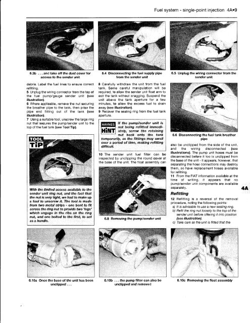
6.3b ... and take off the dust cover for 6.4 Disconnecting the fuel supply pipe 6.5 Unplug the wiring connector from the<br />
access to the sender unit from the sender unit sender unit<br />
debris. Label the fuel lines to ensure correct<br />
refitting.<br />
5 Unplug the wiring connector from the top of<br />
the fuel pump/gauge sender unit (see<br />
illustration).<br />
6 Where applicable, remove the nut securing<br />
the breather pipe to the tank, then prise the<br />
pipe end fitting out of the tank (see<br />
illustration).<br />
7 Using a suitable tool, unscrew the large ring<br />
nut that secures the pump/sender unit to the<br />
top of the fuel tank (see <strong>To</strong>ol Tip).<br />
TOOL<br />
With the limited access available to the<br />
sender unit ring nut, and the fact that<br />
the nut is very tight, we had to make up<br />
a tool to unscrew it. The tool is made<br />
from two metal strips - one bent to fit<br />
across the ring nut to provide two 'legs'<br />
which engage in the ribs on the ring<br />
nut, and one bolted to the first, to act<br />
as a handle.<br />
4<br />
1.1 Oa Once the base of the unit has been<br />
undipped ...<br />
8 Carefully withdraw the unit from the fuel<br />
tank. Some careful manipulation will be<br />
required, to allow the sender unit float arm to<br />
exit the tank without snagging. Suspend the<br />
unit above the tank aperture for a few<br />
minutes, to allow the excess fuel to drain<br />
away (see illustration).<br />
9 Recover the sealing ring from the fuel tank<br />
aperture.<br />
HAYNES<br />
If the pump/sender<br />
not being refitted<br />
unit is<br />
immediately,<br />
screw the retaining<br />
nut back onto the tank<br />
temporarily, as the fittings may swell<br />
over a period<br />
difficult.<br />
of time, making refitting<br />
10 The sender unit fuel filter can be<br />
inspected by unclipping the round cover at<br />
the base of the unit. The float assembly can<br />
6.8 Removing the pump/sender unit<br />
tit<br />
<strong>•</strong><br />
V<br />
6.10b ... the pump filter can also be<br />
undipped and removed<br />
6.6 Disconnecting the fuel tank breather<br />
pipe<br />
also be undipped from the side of the unit,<br />
and the wiring disconnected <strong>•</strong> (see<br />
illustrations). The pump unit hoses must be<br />
disconnected before it too is undipped from<br />
the base of the unit - it appears, however, that<br />
separating the hose connections may destroy<br />
them, so have replacement hoses available<br />
for refitting.<br />
11 From the FIAT information available at the<br />
time of writing, it appears that no<br />
pump/sender unit components are available<br />
<strong>•</strong> separately.<br />
Refitting<br />
12 Refitting is a reversal of the removal<br />
procedure, noting the following points:<br />
a) It is advisable to use a new sealing ring.<br />
b) Refit the ring nut loosely to the top of the<br />
sender unit before offering it into position<br />
(see illustration).<br />
c) Take care as the unit is fitted that the<br />
6.10c Removing the float assembly


