

Bravo & Brava • 1995 To 2000
Bravo & Brava • 1995 To 2000
Bravo & Brava • 1995 To 2000

Create successful ePaper yourself
Turn your PDF publications into a flip-book with our unique Google optimized e-Paper software.
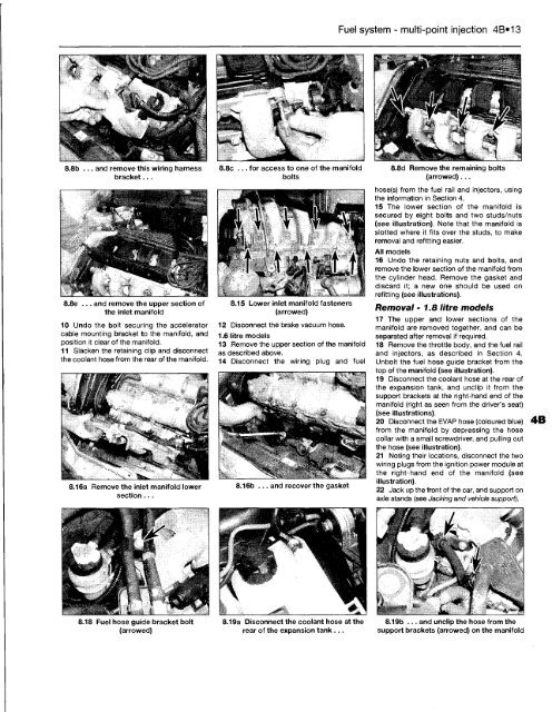
8.8b ... and remove this wiring harness<br />
bracket...<br />
8.8e ... and remove the upper section of<br />
the inlet manifold<br />
10 Undo the bolt securing the accelerator<br />
cable mounting bracket to the manifold, and<br />
position it clear of the manifold.<br />
11 Slacken the retaining clip and disconnect<br />
the coolant hose from the rear of the manifold.<br />
8.16a Remove the inlet manifold lower<br />
section...<br />
8.18 Fuel hose guide bracket bolt<br />
(arrowed)<br />
8.8c ... for access to one of the manifold<br />
bolts<br />
8.15 Lower inlet manifold fasteners<br />
(arrowed)<br />
12 Disconnect the brake vacuum hose.<br />
1.6 litre models<br />
13 Remove the upper section of the manifold<br />
as described above.<br />
14 Disconnect the wiring plug and fuel<br />
8.16b ... and recover the gasket<br />
8.19a Disconnect the coolant hose at the<br />
rear of the expansion tank...<br />
Fuel system - multi-point injection 4B»13<br />
8.8d Remove the remaining bolts<br />
(arrowed)...<br />
hose(s) from the fuel rail and injectors, using<br />
the information in Section 4.<br />
15 The lower section of the manifold is<br />
secured by eight bolts and two studs/nuts<br />
(see illustration). Note that the manifold is<br />
slotted where it fits over the studs, to make<br />
removal and refitting easier.<br />
All models<br />
16 Undo the retaining nuts and bolts, and<br />
remove the lower section of the manifold from<br />
the cylinder head. Remove the gasket and<br />
discard it; a new one should be used on<br />
refitting (see illustrations).<br />
Removal -1.8 litre models<br />
17 The upper and lower sections of the<br />
manifold are removed together, and can be<br />
separated after removal if required.<br />
18 Remove the throttle body, and the fuel rail<br />
and injectors, as described in Section 4.<br />
Unbolt the fuel hose guide bracket from the<br />
top of the manifold (see illustration).<br />
19 Disconnect the coolant hose at the rear of<br />
the expansion tank, and unclip it from the<br />
support brackets at the right-hand end of the<br />
manifold (right as seen from the driver's seat)<br />
(see illustrations).<br />
20 Disconnect the EVAP hose (coloured blue)<br />
from the manifold by depressing the hose<br />
collar with a small screwdriver, and pulling out<br />
the hose (see illustration).<br />
21 Noting their locations, disconnect the two<br />
wiring plugs from the ignition power module at<br />
the right-hand end of the manifold (see<br />
illustration).<br />
22 Jack up the front of the car, and support on<br />
axle stands (see Jacking and vehicle support).<br />
8.19b ... and unclip the hose from the<br />
support brackets (arrowed) on the manifold


