

Bravo & Brava • 1995 To 2000
Bravo & Brava • 1995 To 2000
Bravo & Brava • 1995 To 2000

Create successful ePaper yourself
Turn your PDF publications into a flip-book with our unique Google optimized e-Paper software.
8*6 Driveshafts<br />
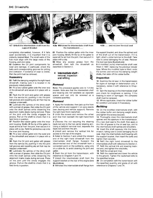
4.7 Unbolt the intermediate shaft from the 4.8a Withdraw the intermediate shaft from<br />
support bracket<br />
the transmission ,..<br />
completely dismantled, however, if it falls<br />
apart accidentally, it is important that it is<br />
correctly reassembled. The small webs of the<br />
hub must align with the large webs of the<br />
housing, and vice versa.<br />
52 Examine the CV joint components for<br />
wear and damage. In particular, check the<br />
balls and corresponding grooves for pitting<br />
and corrosion. If evidence of wear is visible,<br />
then the joint must be renewed.<br />
Reassembly<br />
53 Refit the damping weight to the right-hand<br />
driveshaft, making sure it is located in its<br />
previously noted position.<br />
54 Fit a new rubber gaiter onto the inner end<br />
of the driveshaft and secure it in place with a<br />
clip.<br />
55 Pack the CV joint and gaiter with grease<br />
from the service kit, pushing it into the joint<br />
ball grooves and expelling any air that may be<br />
trapped underneath.<br />
56 Lubricate the splines of the drive shaft<br />
with a smear of grease, then slide the CV joint<br />
onto the shaft splines while observing the<br />
alignment marks made during removal. Press<br />
on the joint until the circlip engages the<br />
groove. Pull on the shaft to check that it is<br />
held firmly in position.<br />
57 Position the rubber gaiter onto the inner<br />
joint housing. Briefly lift the lip of the gaiter to<br />
expel all the air from the joint, then secure it in<br />
place with a clip. Refit the protective cup onto<br />
the inner joint housing.<br />
58 Fit a new rubber gaiter onto the outer end<br />
of the driveshaft and secure it in place with a<br />
clip.<br />
59 Pack the CV joint and gaiter with grease<br />
from the service kit, pushing it into the joint<br />
ball grooves and expelling any air that may be<br />
trapped underneath.<br />
60 Lubricate the splines of the drive shaft<br />
with a smear of grease, then slide the CV joint<br />
onto the shaft splines while observing the<br />
alignment marks made during removal. Press<br />
on the joint until the circlip engages the<br />
groove. Pull-on the shaft to check that it is<br />
held firmly in position.<br />
61 Position the rubber gaiter onto the inner<br />
joint housing. Briefly lift the lip of the gaiter to<br />
expel all the air from the joint, then secure it in<br />
place with a clip.<br />
62 Wipe any excess grease from the<br />
driveshaft, then refit the driveshaft as<br />
described in Section 2.<br />
4 Intermediate shaft <strong>•</strong><br />
removal, inspection<br />
and refitting<br />
Removal<br />
Note: This procedure applies only to 1.8 litre<br />
models. Note also that the intermediate shaft<br />
and bearing are not available as separate<br />
spares and can only be renewed as a<br />
complete assembly.<br />
Removal<br />
1 Apply the handbrake, then jack up the front<br />
of the vehicle and support it on axle stands<br />
(see Jacking and vehicle support). Remove<br />
the right-hand front roadwheel.<br />
2 Undo the screws and remove the wheel<br />
arch liner from beneath the right-hand front<br />
wing.<br />
3 Unscrew the nut securing the steering<br />
track-rod end to the hub carrier steering arm.<br />
Using a balljoint removal tool, separate the<br />
track-rod end from the arm.<br />
4 Unbolt and remove the vertical link for<br />
access to the rear of the engine.<br />
5 Refer to Section 2 and unbolt the inboard<br />
end of the right hand driveshaft from the<br />
intermediate shaft flange. Suspend the<br />
disconnected end of the driveshaft from a<br />
convenient point on the subframe, using wire<br />
or a cable-tie, to avoid straining the joint and<br />
gaiter.<br />
6 Drain the oil from the transmission, with<br />
reference to Chapters 1 and 7A.<br />
7 Unbolt the intermediate shaft from the<br />
support bracket on the rear of the engine (see<br />
illustration).<br />
8 Withdraw the intermediate shaft flange from<br />
4.5b ... and recover the dust seal<br />
the support bracket, and draw the splined end<br />
of the shaft out of the transmission. If it is<br />
tight, attach a slide hammer to the shaft. Take<br />
care to avoid damaging the oil seal. Recover<br />
the dust seal (see illustrations).<br />
9 A modified (solid) intermediate shaft was<br />
fitted in 1997. replacing the previous tubular<br />
type. Where the modified type is fitted, undo<br />
the screws and remove the damping weight<br />
shells, then slide off the rubber buffer.<br />
Inspection<br />
10 Examine the oil seal in the transmission<br />
for signs of damage or deterioration and, if<br />
necessary, renew it with reference to Chapter<br />
7A.<br />
11 Spin the bearing on the intermediate shaft<br />
and check for roughness or seizing. If the<br />
bearing is worn or damaged, the complete<br />
shaft must be renewed.<br />
12 Where applicable, check the rubber buffer<br />
for condition and renew it if necessary.<br />
Refitting<br />
13 On the modified intermediate shaft, refit<br />
the rubber buffer and damping weight shells,<br />
and tighten the screws securely.<br />
14 Thoroughly clean the intermediate shaft<br />
splines and the aperture in the transmission.<br />
Fit a new dust seal to the shaft, then apply a<br />
thin film of grease to the oil seal lips, and to<br />
the intermediate shaft splines and shoulders.<br />
15 Insert the shaft squarely into the transmission,<br />
taking care to avoid damaging the oil<br />
seal. Align the intermediate shaft bearing with<br />
the support bracket, then insert the bolts and<br />
tighten them securely.<br />
16 Refit the right hand driveshaft to the<br />
intermediate shaft with reference to Section 2.<br />
17 Refit the vertical link and steering trackrod<br />
end, and tighten the nuts/bolts.<br />
18 Refit the wheel arch liner.<br />
19 Refit the roadwheel and lower the vehicle<br />
to the ground. Tighten the roadwheel bolts to<br />
the specified torque.<br />
20 On completion refill the transmission with<br />
the specified quantity and grade of oil with<br />
reference to Chapters 1 and 7A.


