

Bravo & Brava • 1995 To 2000
Bravo & Brava • 1995 To 2000
Bravo & Brava • 1995 To 2000

Create successful ePaper yourself
Turn your PDF publications into a flip-book with our unique Google optimized e-Paper software.
not apply grease or oil as this will attack the<br />
rubber.<br />
7 Check the anti-roll bar for signs of damage,<br />
wear or serious corrosion.<br />
Refitting<br />
8 Refitting is a reversal of removal, but tighten<br />
all nuts and bolts to the specified torque<br />
where given.<br />
7 Front suspension subframe - |t-=<br />
removal and refitting ^<br />
Removal<br />
1 Apply the handbrake, then jack up the front<br />
of the vehicle and support it on axle stands<br />
(see Jacking and vehicle support). Remove<br />
both front roadwheels.<br />
2 Remove the exhaust front downpipe with<br />
reference to Chapter 4C.<br />
3 Remove both front suspension lower arms<br />
as described in Section 4.<br />
4 Remove the anti-roll bar as described in<br />
Section 6.<br />
5 Unbolt the rear engine mounting from the<br />
subframe, then unbolt the bracket from the<br />
transmission and withdraw the mounting and<br />
bracket from under the vehicle.<br />
6 Undo the screws and remove the exhaust<br />
heatshield from the underbody.<br />
7 Unscrew and remove the two central bolts<br />
securing the steering gear to the subframe.<br />
8 Support the weight of the subframe on a<br />
trolley jack and length of wood.<br />
9 Unscrew and remove the remaining<br />
mounting bolts and lower the subframe to the<br />
ground. Withdraw the subframe from under<br />
the car.<br />
Refitting<br />
10 Lift the subframe on the trolley jack, and<br />
insert the mounting bolts, hand-tight at this<br />
stage.<br />
11 Using two 12.0 mm diameter metal rods<br />
inserted through the two holes at the rear of the<br />
subframe, align the subframe, then tighten the<br />
mounting bolts progressively to the specified<br />
torque.<br />
12 Insert and tighten the steering gear<br />
mounting bolts to the specified torque.<br />
-<br />
k ***<br />
9.3 Rear shock absorber lower mounting<br />
bolt<br />
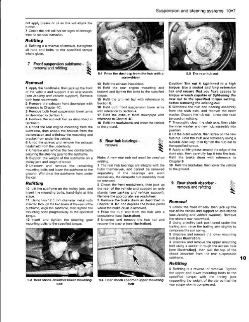
8.4 Prise the dust cap from the hub with a<br />
screwdriver<br />
13 Refit the exhaust heatshield.<br />
14 Refit the rear engine mounting and<br />
bracket and tighten the bolts to the specified<br />
torque.<br />
15 Refit the anti-roll bar with reference to<br />
Section 6.<br />
16 Refit both front suspension lower arms<br />
with reference to Section 4.<br />
17 Refit the exhaust front downpipe with<br />
reference to Chapter 4C.<br />
18 Refit the roadwheels and lower the vehicle<br />
to the ground.<br />
8 Rear hub bearings - §^<br />
renewal Sjk<br />
Note: A new rear hub nut must be used on<br />
refitting.<br />
1 The rear hub bearings are integral with the<br />
hubs themselves, and cannot be renewed<br />
separately. If the bearings are worn<br />
excessively, the complete hub assembly must<br />
be renewed.<br />
2 Chock the front roadwheels, then jack up<br />
the rear of the vehicle and support on axle<br />
stands (see Jacking and vehicle support).<br />
Remove the appropriate rear roadwheel.<br />
3 Remove the brake drum as described in<br />
Chapter 9. Do not depress the brake pedal<br />
whilst the brake drum is removed.<br />
4 Prise the dust cap from the hub with a<br />
screwdriver (see illustration).<br />
5 Unscrew and remove the hub nut and<br />
recover the washer (see illustration).<br />
9.4 Rear shock absorber upper mounting<br />
bolt<br />
Suspension and steering systems 10«7<br />
8.5 The rear hub nut<br />
Caution: The nut is tightened to a high<br />
torque. Use a socket and long extension<br />
bar and ensure that you have access to<br />
torque wrench capable of tightening the<br />
new nut to the specified torque setting,<br />
before removing the existing nut.<br />
6 Withdraw the hub and bearing assembly<br />
from the stub axle, and recover the inner<br />
washer. Discard the hub nut - a new one must<br />
be used on refitting.<br />
7 Thoroughly clean the stub axle, then slide<br />
the inner washer and new hub assembly into<br />
position.<br />
8 Fit the outer washer, then screw on the new<br />
hub nut. Hold the stub axle stationary using a<br />
suitable Allen key, then tighten the hub nut to<br />
the specified torque.<br />
9 Apply a little grease around the edge of the<br />
dust cap, then carefully tap it into the hub.<br />
Refit the brake drum with reference to<br />
Chapter 9.<br />
10 Refit the roadwheel then lower the vehicle<br />
to the ground.<br />
9 Rear shock absorber -<br />
removal and refitting ^<br />
Removal<br />
1 Chock the front wheels, then jack up the<br />
rear of the vehicle and support on axle stands<br />
(see Jacking and vehicle support). Remove<br />
the relevant rear roadwheel.<br />
2 Using a trolley jack positioned under the<br />
trailing arm, raise the trailing arm slightly to<br />
compress the coil spring.<br />
3 Unscrew and remove the lower mounting<br />
bolt (see illustration).<br />
4 Unscrew and remove the upper mounting<br />
bolt using a socket through the access hole<br />
(see illustration), then pull the top of the<br />
shock absorber from the rear suspension<br />
subframe.<br />
Refitting<br />
5 Refitting is a reversal of removal. Tighten<br />
the upper and lower mounting bolts to the<br />
specified torque with the trolley jack<br />
supporting the weight of the car so that the<br />
rear suspension is compressed.


