

Bravo & Brava • 1995 To 2000
Bravo & Brava • 1995 To 2000
Bravo & Brava • 1995 To 2000

Create successful ePaper yourself
Turn your PDF publications into a flip-book with our unique Google optimized e-Paper software.
5B»4 Ignition system<br />
inside the insulation so that no visible evidence<br />
betrays the fault, but this usually only occurs<br />
where the wiring loom has been incorrectly<br />
routed so that it is stretched taut or kinked<br />
sharply; either of these conditions should be<br />
obvious on even a casual inspection. If this is<br />
thought to have happened and the fault proves<br />
elusive, the suspect section of wiring should<br />
be checked very carefully during the more<br />
detailed checks which follow.<br />
7 Depending on the extent of the problem,<br />
damaged wiring may be repaired by rejoining<br />
the break or splicing-in a new length of wire,<br />
using solder to ensure a good connection,<br />
and remaking the insulation with adhesive<br />
insulating tape or heat-shrink tubing, as<br />
desired. If the damage is extensive, given the<br />
implications for the vehicle's future reliability,<br />
the best long-term answer may well be to<br />
renew that entire section of the loom, however<br />
expensive this may appear.<br />
8 When the actual damage has been<br />
repaired, ensure that the wiring loom is rerouted<br />
correctly, so that it is clear of other<br />
components, is not stretched or kinked, and is<br />
secured out of harm's way using the plastic<br />
clips, guides and ties provided.<br />
9 Check all electrical connectors, ensuring<br />
that they are clean, securely fastened, and<br />
that each is locked by its plastic tabs or wire<br />
clip, as appropriate. If any connector shows<br />
external signs of corrosion (accumulations of<br />
white or green deposits, or streaks of 'rust'),<br />
or if any is thought to be dirty, it must be<br />
unplugged and cleaned using electrical<br />
contact cleaner. If the connector pins are<br />
severely corroded, the connector must be<br />
renewed; note that this may mean the renewal<br />
of that entire section of the loom.<br />
10 If the cleaner completely removes the<br />
corrosion to leave the connector in a<br />
satisfactory condition, it would be wise to<br />
pack the connector with a suitable material<br />
which will exclude dirt and moisture, and<br />
prevent the corrosion from occurring again; a<br />
FIAT dealer may be able to recommend a<br />
suitable product.<br />
11 All models have an inductive sensor which<br />
determines crankshaft speed and TDC<br />
position. On an older engine, it is possible that<br />
the tip of the sensor may become<br />
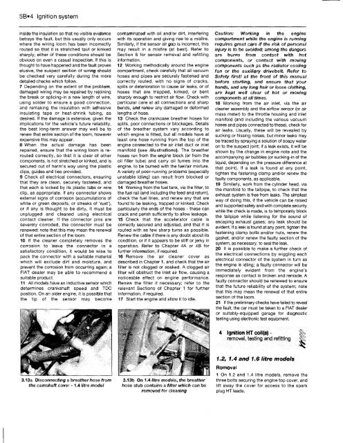
3.13a Disconnecting a breather hose from<br />
the camshaft cover -1.4 litre model<br />
contaminated with oil and/or dirt, interfering<br />
with its operation and giving rise to a misfire.<br />
Similarly, if the sensor air gap is incorrect, this<br />
may result in a misfire (at best). Refer to<br />
Section 6 for sensor removal and refitting<br />
information.<br />
12 Working methodically around the engine<br />
compartment, check carefully that all vacuum<br />
hoses and pipes are securely fastened and<br />
correctly routed, with no signs of cracks,<br />
splits or deterioration to cause air leaks, or of<br />
hoses that are trapped, kinked, or bent<br />
sharply enough to restrict air flow. Check with<br />
particular care at all connections and sharp<br />
bends, and renew any damaged or deformed<br />
lengths of hose.<br />
13 Check the crankcase breather hoses for<br />
splits, poor connections or blockages. Details<br />
of the breather system vary according to<br />
which engine is fitted, but all models have at<br />
least one hose running from the top of the<br />
engine connected to the air inlet duct or inlet<br />
manifold (see illustrations). The breather<br />
hoses run from the engine block (or from the<br />
oil filler tube) and carry oil fumes into the<br />
engine, to be burned with the fuel/air mixture.<br />
A variety of poor-running problems (especially<br />
unstable idling) can result from blocked or<br />
damaged breather hoses.<br />
14 Working from the fuel tank, via the filter, to<br />
the fuel rail (and including the feed and return),<br />
check the fuel lines, and renew any that are<br />
found to be leaking, trapped or kinked. Check<br />
particularly the ends of the hoses - these can<br />
crack and perish sufficiently to allow leakage.<br />
15 Check that the accelerator cable is<br />
correctly secured and adjusted, and that it is<br />
routed with as few sharp turns as possible.<br />
Renew the cable if there is any doubt about its<br />
condition, or if it appears to be stiff or jerky in<br />
operation. Refer to Chapter 4A or 4B for<br />
further information, if required.<br />
16 Remove the air cleaner cover as<br />
described in Chapter 1, and check that the air<br />
filter is not clogged or soaked. A clogged air<br />
filter will obstruct the inlet air flow, causing a<br />
noticeable effect on engine performance.<br />
Renew the filter if necessary; refer to the<br />
relevant Sections of Chapter 1 for further<br />
information, if required.<br />
17 Start the engine and allow it to idle.<br />
3.13b On 1.4 litre models, the breather<br />
hose stub contains a filter which can be<br />
removed for cleaning<br />
Caution: Working in the engine<br />
compartment while the engine is running<br />
requires great care if the risk of personal<br />
injury is to be avoided; among the dangers<br />
are burns from contact with hot<br />
components, or contact with moving<br />
components such as the radiator cooling<br />
fan or the auxiliary drivebelt. Refer to<br />
Safety first! at the front of this manual<br />
before starting, and ensure that your<br />
hands, and any long hair or loose clothing,<br />
are kept well clear of hot or moving<br />
components at all times.<br />
18 Working from the air inlet, via the air<br />
cleaner assembly and the airflow sensor (or air<br />
mass meter) to the throttle housing and inlet<br />
manifold (and including the various vacuum<br />
hoses and pipes connected to these), check for<br />
air leaks. Usually, these will be revealed by<br />
sucking or hissing noises, but minor leaks may<br />
be traced by spraying a solution of soapy water<br />
on to the suspect joint; if a leak exists, it will be<br />
shown by the change in engine note and the<br />
accompanying air bubbles (or sucking-in of the<br />
liquid, depending on the pressure difference at<br />
that point). If a leak is found at any point,<br />
tighten the fastening clamp and/or renew the<br />
faulty components, as applicable.<br />
19 Similarly, work from the cylinder head, via<br />
the manifold to the tailpipe, to check that the<br />
exhaust system is free from leaks. The simplest<br />
way of doing this, if the vehicle can be raised<br />
and supported safely and with complete security<br />
while the check is made, is to temporarily block<br />
the tailpipe while listening for the sound of<br />
escaping exhaust gases; any leak should be<br />
evident. If a leak is found at any point, tighten the<br />
fastening clamp bolts and/or nuts, renew the<br />
gasket, and/or renew the faulty section of the<br />
system, as necessary, to seal the leak.<br />
20 It is possible to make a further check of<br />
the electrical connections by wiggling each<br />
electrical connector of the system in turn as<br />
the engine is idling; a faulty connector will be<br />
immediately evident from the engine's<br />
response as contact is broken and remade. A<br />
faulty connector should be renewed to ensure<br />
that the future reliability of the system; note<br />
that this may mean the renewal of that entire<br />
section of the loom.<br />
21 If the preliminary checks have failed to reveal<br />
the fault, the car must be taken to a FIAT dealer<br />
or suitably-equipped garage for diagnostic<br />
testing using electronic test equipment.<br />
4 Ignition HT coil(s) - f^><br />
removal, testing and refitting<br />
1.2, 1.4 and 1.6 litre models<br />
Removal<br />
1 On 1.2 and 1.4 litre models, remove the<br />
three bolts securing the engine top cover, and<br />
lift away the cover for access to the spark<br />
plug HT leads.


