

Bravo & Brava • 1995 To 2000
Bravo & Brava • 1995 To 2000
Bravo & Brava • 1995 To 2000

You also want an ePaper? Increase the reach of your titles
YUMPU automatically turns print PDFs into web optimized ePapers that Google loves.
4B«14 Fuel system - multi-point injection<br />
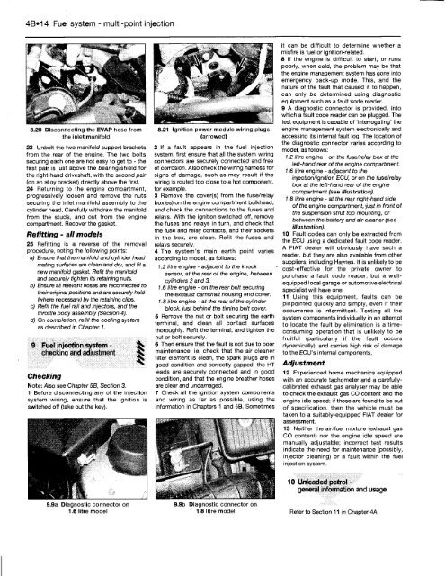
8.20 Disconnecting the EVAP hose from<br />
the inlet manifold<br />
23 Unbolt the two manifold support brackets<br />
from the rear of the engine. The two bolts<br />
securing each one are not easy to get to - the<br />
first pair is just above the bearing/shield for<br />
the right-hand driveshaft, with the second pair<br />
(on an alloy bracket) directly above the first.<br />
24 Returning to the engine compartment,<br />
progressively loosen and remove the nuts<br />
securing the inlet manifold assembly to the<br />
cylinder head. Carefully withdraw the manifold<br />
from the studs, and out from the engine<br />
compartment. Recover the gasket.<br />
Refitting - all models<br />
25 Refitting is a reverse of the removal<br />
procedure, noting the following points:<br />
a) Ensure that the manifold and cylinder head<br />
mating surfaces are clean and dry, and fit a<br />
new manifold gasket. Refit the manifold<br />
and securely tighten its retaining nuts.<br />
b) Ensure all relevant hoses are reconnected to<br />
their original positions and are securely held<br />
(where necessary) by the retaining clips.<br />
c) Refit the fuel rail and injectors, and the<br />
throttle body assembly (Section 4).<br />
d) On completion, refill the cooling system<br />
as described in Chapter 1.<br />
9 Fuel injection system - gS<br />
Checking<br />
checking and adjustment S<br />
Note: Also see Chapter 5B, Section 3.<br />
1 Before disconnecting any of the injection<br />
system wiring, ensure that the ignition is<br />
switched off (take out the key).<br />
9.9a Diagnostic connector on<br />
1.6 litre model<br />
8.21 Ignition power module wiring plugs<br />
(arrowed)<br />
2 If a fault appears in the fuel injection<br />
system, first ensure that all the system wiring<br />
connectors are securely connected and free<br />
of corrosion. Also check the wiring harness for<br />
signs of damage, such as may result if the<br />
wiring is routed too close to a hot component,<br />
for example.<br />
3 Remove the cover(s) from the fuse/relay<br />
box(es) on the engine compartment bulkhead,<br />
and check the connections to the fuses and<br />
relays. With the ignition switched off, remove<br />
the fuses and relays in turn, and check that<br />
the fuse and relay contacts, and their sockets<br />
in the box, are clean. Refit the fuses and<br />
relays securely.<br />
4 The system's main earth point varies<br />
according to model, as follows:<br />
1.2 litre engine - adjacent to the knock<br />
sensor, at the rear of the engine, between<br />
cylinders 2 and 3.<br />
1.6 litre engine - on the rear bolt securing<br />
the exhaust camshaft housing end cover.<br />
1.8 litre engine - at the rear of the cylinder<br />
block, just behind the timing belt cover.<br />
5 Remove the nut or bolt securing the earth<br />
terminal, and clean all contact surfaces<br />
thoroughly. Refit the terminal, and tighten the<br />
nut or bolt securely.<br />
6 Then ensure that the fault is not due to poor<br />
maintenance; ie, check that the air cleaner<br />
filter element is clean, the spark plugs are in<br />
good condition and correctly gapped, the HT<br />
leads are securely connected and in good<br />
condition, and that the engine breather hoses<br />
are clear and undamaged.<br />
7 Check all the ignition system components<br />
and wiring as far as possible, using the<br />
information in Chapters 1 and 5B. Sometimes<br />
9.9b Diagnostic connector on<br />
1.8 litre model<br />
it can be difficult to determine whether a<br />
misfire is fuel or ignition-related.<br />
8 If the engine is difficult to start, or runs<br />
poorly, when cold, the problem may be that<br />
the engine management system has gone into<br />
emergency back-up mode. This, and the<br />
nature of the fault that caused it to happen,<br />
can only be determined using diagnostic<br />
equipment such as a fault code reader.<br />
9 A diagnostic connector is provided, into<br />
which a fault code reader can be plugged. The<br />
test equipment is capable of 'interrogating' the<br />
engine management system electronically and<br />
accessing its internal fault log. The location of<br />
the diagnostic connector varies according to<br />
model, as follows:<br />
1.2 litre engine - on the fuse/relay box at the<br />
left-hand rear of the engine compartment.<br />
1.6 litre engine - adjacent to the<br />
injection/ignition ECU, or on the fuse/relay<br />
box at the left-hand rear of the engine<br />
compartment (see illustration).<br />
1.8 litre engine - at the rear right-hand side<br />
of the engine compartment, just in front of<br />
the suspension strut top mounting, or<br />
between the battery and air cleaner (see<br />
illustration).<br />
10 Fault codes can only be extracted from<br />
the ECU using a dedicated fault code reader.<br />
A FIAT dealer will obviously have such a<br />
reader, but they are also available from other<br />
suppliers, including Haynes. It is unlikely to be<br />
cost-effective for the private owner to<br />
purchase a fault code reader, but a wellequipped<br />
local garage or automotive electrical<br />
specialist will have one.<br />
11 Using this equipment, faults can be<br />
pinpointed quickly and simply, even if their<br />
occurrence is intermittent. Testing all the<br />
system components individually in an attempt<br />
to locate the fault by elimination is a timeconsuming<br />
operation that is unlikely to be<br />
fruitful (particularly if the fault occurs<br />
dynamically), and carries high risk of damage<br />
to the ECU'S internal components.<br />
Adjustment<br />
12 Experienced home mechanics equipped<br />
with an accurate tachometer and a carefullycalibrated<br />
exhaust gas analyser may be able<br />
to check the exhaust gas CO content and the<br />
engine idle speed; if these are found to be out<br />
of specification, then the vehicle must be<br />
taken to a suitably-equipped FIAT dealer for<br />
assessment.<br />
13 Neither the air/fuel mixture (exhaust gas<br />
CO content) nor the engine idle speed are<br />
manually adjustable; incorrect test results<br />
indicate the need for maintenance (possibly,<br />
injector cleaning) or a fault within the fuel<br />
injection system.<br />
10 Unleaded petrol -<br />
general information and usage<br />
Refer to Section 11 in Chapter 4A.


