

Bravo & Brava • 1995 To 2000
Bravo & Brava • 1995 To 2000
Bravo & Brava • 1995 To 2000

You also want an ePaper? Increase the reach of your titles
YUMPU automatically turns print PDFs into web optimized ePapers that Google loves.
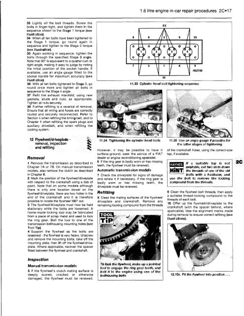
33 Lightly oil the bolt threads. Screw the<br />
bolts in finger-tight, and tighten them in the<br />
sequence shown to the Stage 1 torque (see<br />
illustration).<br />
34 When all ten bolts have been tightened to<br />
the Stage 1 torque, go round again in<br />
sequence and tighten to the Stage 2 torque<br />
(see illustration).<br />
35 Again working in sequence, tighten the<br />
bolts through the specified Stage 3 angle.<br />
Note that 90° is equivalent to a quarter-turn or<br />
right-angle, making it easy to judge by noting<br />
the initial position of the socket handle. If<br />
available, use an angle gauge fitted to the<br />
socket handle for maximum accuracy (see<br />
illustration).<br />
36 With all ten bolts tightened to Stage 3, go<br />
round once more and tighten all bolts in<br />
sequence to the Stage 4 angle.<br />
37 Refit the exhaust manifold, using new<br />
gaskets, studs and nuts, as appropriate.<br />
Tighten all nuts securely.<br />
38 Further refitting is a reversal of removal.<br />
Ensure that all wiring and hoses are correctly<br />
routed and securely reconnected. Refer to<br />
Section 4 when refitting the timing belt, and to<br />
Chapter 1 when refitting the spark plugs and<br />
auxiliary drivebelt, and when refilling the<br />
cooling system.<br />
12 Flywheel/driveplate -<br />
removal, inspection<br />
and refitting<br />
Removal<br />
1 Remove the transmission as described in<br />
Chapter 7A or 7B. On manual transmission<br />
models, also remove the clutch as described<br />
in Chapter 6.<br />
2 Mark the position of the flywheel/driveplate<br />
with respect to the crankshaft using a dab of<br />
paint. Note that on some models although<br />
there is only one location dowel on the<br />
flywheel/driveplate, there are two holes in the<br />
end of the crankshaft and it is therefore<br />
possible to locate the flywheel 180° out.<br />
3 The flywheel/driveplate must now be held<br />
stationary while the bolts are loosened. A<br />
home-made locking tool may be fabricated<br />
from a piece of scrap metal and used to lock<br />
the ring gear. Bolt the tool to one of the<br />
transmission bellhousing mounting holes (see<br />
<strong>To</strong>ol Tip).<br />
4 Support the flywheel as the bolts are<br />
loosened - the flywheel is very heavy. Unscrew<br />
and remove the mounting bolts, take off the<br />
mounting plate, then lift off the flywheel/driveplate.<br />
Where applicable, recover the spacer<br />
fitted between the flywheel and crankshaft.<br />
Inspection<br />
Manual transmission models<br />
5 If the flywheel's clutch mating surface is<br />
deeply scored, cracked or otherwise<br />
damaged, the flywheel must be renewed.<br />
'o<br />
1°<br />
1.6 litre engine in-car repair procedures 2017<br />
EX<br />
8 \ 6 / / 2 \ \ 5 / 10<br />
7<br />
_i o<br />
1 1 1 2<br />
i ° \"<br />
/ 3<br />
11.34 Tightening the cylinder head bolts<br />
However, it may be possible to have it<br />
surface-ground; seek the advice of a FIAT<br />
dealer or engine reconditioning specialist.<br />
6 If the ring gear is badly worn or has missing<br />
teeth, the flywheel must be renewed.<br />
Automatic transmission models<br />
7 Check the driveplate for signs of damage<br />
and renew it if necessary. If the ring gear is<br />
badly worn or has missing teeth, the<br />
driveplate must be renewed.<br />
Refitting<br />
\<br />
/ o \ ,A o<br />
o<br />
1<br />
IN<br />
i o Y""<br />
o'<br />
°,<br />
/ 4 \ 9<br />
HZ2750<br />
11.33 Cylinder head bolt tightening sequence<br />
8 Clean the mating surfaces of the flywheel/<br />
driveplate and crankshaft. Remove any<br />
remaining locking compound from the threads<br />
TOOL<br />
7b lock the flywheel, make up a pointed<br />
tool to engage the ring gear teeth, and<br />
bolt it to the engine using one of the<br />
bellhousing bolts<br />
11.35 Use an angle gauge if possible for<br />
the latter stages of tightening<br />
of the crankshaft holes, using the correct-size<br />
tap, if available.<br />
HAYNES<br />
If a suitable tap is not<br />
available, cut two slots down<br />
the threads of one of the old<br />
bolts with a hacksaw, and<br />
use the bolt to remove the locking<br />
compound from the threads.<br />
9 Clean the flywheel bolt threads, then apply<br />
a suitable thread-locking compound to the<br />
threads of each bolt.<br />
10 Offer up the flywheel/driveplate to the<br />
crankshaft (with the spacer behind, where<br />
applicable). Use the alignment marks made<br />
during removal to ensure correct refitting (see<br />
illustrations).<br />
12.10a Fit the flywheel into position .


